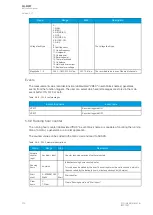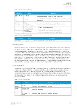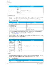
Table. 6.1.2 - 343. PTP time synchronization settings.
Name
Range
Description
Role
0: Auto
(Default)
1:
Master
2: Slave
In Auto mode, the device can take both the role of a clock source and clock consumer, In Master
mode the device is forced to concider it self to be a clock source. In Slave mode the device is forced
to be a clock consumer.
Mechanism
0: P2P
(Default)
1: E2E
Delay measurement mechanism used. Peer-to-peer can utilize the PTP enabled switches as
transparent ro boundary clocks while End-to-end must be used if non-PTP enabled switches are
found in the network.
Domain
number
0...255
PTP devices can be set to belong to a grouping called domain. Devices in same domain is primearly
being synchronized together.
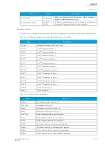
Status indications
The following status indications are available in
Communication
→
Synchronization
→
PTP menu.
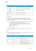
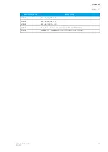
Table. 6.1.2 - 344. PTP status indications
Name
Description
State
State of the PTP application (Master, Slave, Listening)
Best master
Identification of best master in network. Id consist of MAC address plus id number
Last receive
Time when last synchronization frame was received.
Message sent
Diagnostic message counter
Message receive
Diagnostic message counter
PTP timesource
Diagnostic number describing the current time source
6.1.3 Modbus/TCP and Modbus/RTU
The device supports both Modbus/TCP and Modbus/RTU communication. Modbus/TCP uses the
Ethernet connection to communicate with Modbus/TCP clients. Modbus/RTU is a serial protocol that
can be selected for the available serial ports.
The following Modbus function types are supported:
• Read multiple holding registers (function code 3)
• Write single holding register (function code 6)
• Write multiple holding registers (function code 16)
• Read/Write multiple registers (function code 23)
The following data can be accessed using both Modbus/TCP and Modbus/RTU:
• Device measurements
• Device I/O
• Commands
• Events
• Time
Once the configuration file has been loaded, the user can access the Modbus map of the relay via the
AQtivate software (
Tools
→
Communication
→
Modbus Map). Please note that holding registers start
from 1. Some masters might begin numbering holding register from 0 instead of 1; this will cause an
offset of 1 between the relay and the master. Modbus map can be edited with Modbus Configurator
(
Tools
→
Communication
→
Modbus Configurator).
A
AQ
Q-M257
-M257
Instruction manual
Version: 2.07
424
© Arcteq Relays Ltd
IM00021
Summary of Contents for AQ-M257
Page 1: ...AQ M257 Motor protection IED Instruction manual...
Page 2: ......


