General settings
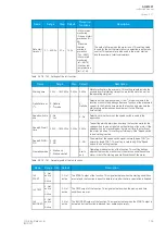
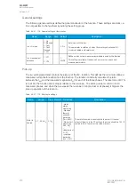
The following general settings define the general behavior of the function. These settings are static i.e.
it is not possible to change them by editing the setting group.
Table. 5.4.21 - 178. General settings of the function.
Name
Range
Step Default
Description
Im> LN mode
1: On
2: Blocked
3: Test
4: Test/
Blocked
5: Off
-
0: On
Set mode of MJP block.
This parameter is visible only when
Allow setting of individual LN
mode is enabled in General menu.
Im> measurement
selection
1: CT1
2: CT2
-
1:
POW1
Defines which current measurement module is used by the function.
This setting is available if the device has more than one current
measurement module.
Pick-up
The
I
set
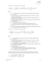
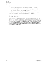
setting parameter controls the pick-up of the Im> function. This defines the maximum allowed
measured current before action from the function. The function constantly calculates the ratio
between the
I
set
and the measured magnitude (
I
m
) for each of the three phases. The reset ratio of 97 %
is built into the function and is always relative to the
I
set
value. The setting value is common for all
measured phases, and when the
I
m
exceeds the
I
set
value (in single, dual or all phases) it triggers the
pick-up operation of the function.
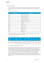
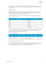
Table. 5.4.21 - 179. Motor data settings.
Name
Range
Step Default Prot.funcs.
Description
Motor In
Scaled
0.1... 40.0xI
n
0.1xI
n
-
- Motor
status
monitoring
- Machine
thermal
overload
protection
(Tm>; 49M)
- Motor start
monitoring
(Ist>; 48)
-
Undercurrent
(I<; 37)
- Load jam
protection
(Im>; 51M)
The motor's nominal current scaled to per unit. If the user
selects
Object In in the CT settings, this value should be 1.00. If
scaled to the CT nominal, this value may vary.
A
AQ
Q-M257
-M257
Instruction manual
Version: 2.07
212
© Arcteq Relays Ltd
IM00021
Summary of Contents for AQ-M257
Page 1: ...AQ M257 Motor protection IED Instruction manual...
Page 2: ......


