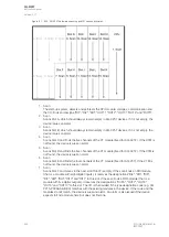
Name
Range
Description
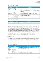
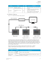
Quality of Modbus Sub
unit 1...32
0: OK
1: Old data
2: Data
questionable
3: Modbus
error
4: Send fail
5: Receive fail
Quality of each connected sub unit.
Imported signals
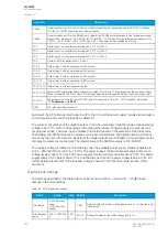
Modbus Gateway supports importing of measurements, bits, double bits, counters and integer signals.
Up to 128 signals can be imported of each signal type with the exception of double bits (32).
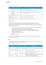
Table. 6.4 - 365. Imported signals
Name
Range
Imported measurement 1-128
-3.4E+38...3.4E+38
Imported bit signal 1-128
0...1
Imported double bit data 1-32
0...3
Imported counter data 1-128
0...4294967295
Imported integer signal 1-128
-2147483648...2147483647
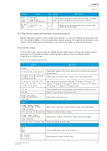
To assign the signals use Modbus Gateway editor (
Tools
→
Communication
→
Modbus Gateway).
Detailed description of this tool can be found in
AQtivate 200 Instruction
manual (
All imported signals can be given a description. The description will be displayed in most of menus with
the signal (logic editor, matrix, block settings etc.).
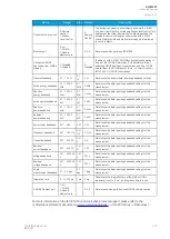
Table. 6.4 - 366. Imported signal user description.
Name
Range
Default
Description
Describe
measurement x
1...31
characters
Acq.
Meas x
User settable description for the signal. This description is used in several
menu types for easier identification.
Describe bit signal
x
Acq. Bit x
Describe doube
bit signal x
Acq.
Binary x
Describe counter
signal x
Acq.
Counter x
Describe integer
signal x
Acq.
Integer x
Events
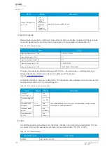
The Modbus Gateway generates events the status changes in imported bits and double bits. The user
can select which event messages are stored in the main event buffer: ON, OFF, or both.
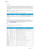
Table. 6.4 - 367. Event messages
Event block name
Event names
MGWB1
Bit 1...Bit 32 (ON, OFF)
A
AQ
Q-M257
-M257
Instruction manual
Version: 2.07
438
© Arcteq Relays Ltd
IM00021
Summary of Contents for AQ-M257
Page 1: ...AQ M257 Motor protection IED Instruction manual...
Page 2: ......


