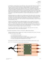
Calculating the generated differential current — The non-biased settings
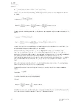
Now that the biased characteristic is set, we consider the settings for the non-biased stage I
di>Pick-up
.
The purpose of this stage is to ensure fast and selective tripping of faults inside the differential zone,
and also to ensure a stable operation on heavy outside faults. This stage operates only on the
measured absolute differential current and is not blocked by harmonics or bias restraints. The setting of
the stage should be based on the weakest full saturation of the CT under worst-case fault conditions
because then only the other side current is measured and all current seen is differential current.
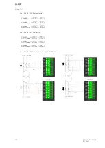
Let us calculate the maximum three-phase short-circuit current on the LV side in our example case
from earlier:
On the HV side this current is seen as:
Next, let us remind ourselves of the given CT ratings for our example:
CT
pri,HV
= 150/5A (10P10)
CT
pri,LV
= 1200/5A (5P10)
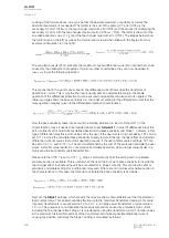
Now we can calculate the secondary currents:
This is the theoretical maximum of the current flowing in the CTs, when a bolted and symmetrical three-
phase fault occurs in the LV side of the transformer. Based on the previous calculations, we can see
that the HV side maximum current is approximately 15 times higher than the CT rating, and the LV side
appr. 19 times higher. No full CT saturation should be seen in either side even though the accuracy
limit factor for both CTs is ten times the nominal. The protection class information in the CT ratings tell
us that the CT output is for both CTs ten times the rated current in their given measurement class (5 %
and 10 %, respectively). However, this is related to the nominal burden that is normally very high
compared to the CT input in modern protection relays
.
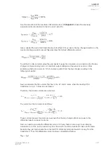
Next, the real CT accuracy limit factor needs to be checked in both CTs, in both sides. This check has
much important initial data: the VA of the CTs on both sides, the length of the wiring between the relay
and the CTs, the connection between the CTs, as well as the cross-section and material of the wires.
Let us begin with the burden the wiring causes to the relay, and calculate the resistance in a
conductor:
A
AQ
Q-M257
-M257
Instruction manual
Version: 2.07
© Arcteq Relays Ltd
IM00021
299
Summary of Contents for AQ-M257
Page 1: ...AQ M257 Motor protection IED Instruction manual...
Page 2: ......

