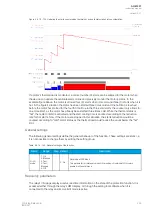
The variables the user can set are binary signals from the system. The blocking signal needs to reach
the device minimum of 5 ms before the set operating delay has passed in order for the blocking to
activate in time.
Events and registers
The load jam protection function (abbreviated "MJP" in event block names) generates events and
registers from the status changes in START, TRIP, and BLOCKED. The user can select which event
messages are stored in the main event buffer: ON, OFF, or both.
The events triggered by the function are recorded with a time stamp and with process data values.
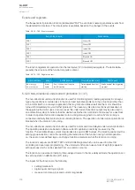
Table. 5.4.21 - 182. Event messages.
Event block name
Event names
MJP1
Start ON
MJP1
Start OFF
MJP1
Trip ON
MJP1
Trip OFF
MJP1
Block ON
MJP1
Block OFF
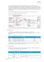
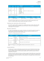
The function registers its operation into the last twelve (12) time-stamped registers. The register of the
function records the ON event process data for START, TRIP or BLOCKED. The table below
presents the structure of the function's register content.
Table. 5.4.21 - 183. Register content.
Date and time Event
Fault type
Pre-trigger
current
Fault
current
Pre-fault
current
Trip time
remaining
Used SG
dd.mm.yyyy
hh:mm:ss.mss
Event
name
L1-G…L1-L2-L3 Start/Trip
-20ms current
Start/Trip
current
Start
-200ms
current
0 ms...1800s
Setting group
1...8 active
5.4.22 Power factor protection (PF<; 55)
The power factor protection function is the ratio of active power to apparent power (cos φ = P/S). In a
fully resistive load the power factor is 1.00. In partially inductive loads the power factor is under 1.00.
Power factor protection cannot detect a power factor value that is too low.
A
AQ
Q-M257
-M257
Instruction manual
Version: 2.07
© Arcteq Relays Ltd
IM00021
217
Summary of Contents for AQ-M257
Page 1: ...AQ M257 Motor protection IED Instruction manual...
Page 2: ......

