background image

APACHE-E  SWIFT/LOGO10                       PAGE #  18 

DAWSON’S


APPROACH E GI EERI G  

                                                                                                                         AH-64A ELECTRIC 

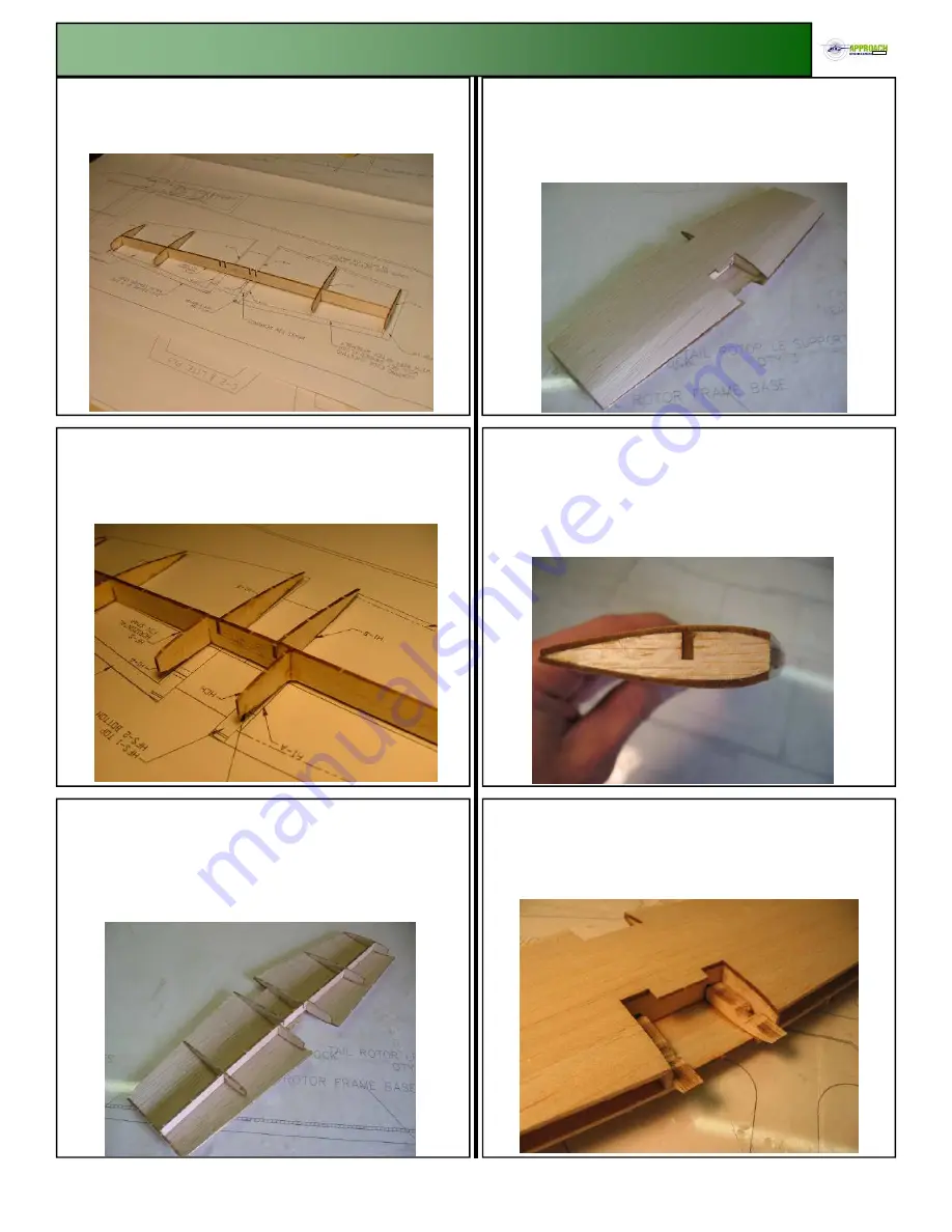
15.1  

Punch out the 3/32” horizontal fin spar, HF-S, and hori-

zontal fin ribs H-2, and H-3.  Glue the ribs to the spar in their 
corresponding notches. 

15.2  

Punch out the 3/32” horizontal fin ribs H-1A, H-1B.  

Glue the two H1-A ribs in the outside notches facing toward the 
front edge.  H1-B ribs are glued to the inside notches facing 
toward the trailing edge. 

15.3  

Punch out the horizontal fin lower sheeting, HF-1, and 

place the spar assembly in the proper place.  The wing spar will 
line up with the center sheeting cut out and be flush with the 
edge.  Start by applying CA+ to the lower surface of the spar.  
Once dried apply CA+ to the lower surface of the ribs behind 
the spar to the trailing edge.  Press the sheeting up into place.  

15.4  

Punch out the 1/16” balsa upper sheeting HF-2.  Sheet 

the top of the horizontal fin by aligning the trailing edge of the 
upper and lower sheeting.  Apply CA+ to the upper surface of 
the spar, the ribs behind the spar and trailing edge.  Press the 
sheeting back and hold the trailing edge together. 


15.5  

Glue the upper and lower surfaces of the balsa leading 

edge and press the sheeting down into place.  Cut off the excess 
sheeting along the leading edge.  Using a flat sanding block 
sand the leading edge flat.


15.6   

Turn the horizontal fin assembly over to expose the box 

bay.  Punch out the two ¼” light ply horizontal fin supports 
HFS-1.  Using CA+ glue the supports up against the upper 
sheeting, H1-A, and the wing spar. 


15.0  HORIZO TAL FI  
         ASSEMBLY 

Summary of Contents for AH-64A APACHE SWIFT/LOGO 10

Page 1: ...A H 6 4 A A P A C H E S W I F T L O G O 1 0 APPROACH E GI EERI G www ApproachEngineering com ...

Page 2: ...ve Muncie IN 47302 800 435 9262 2 Please inspect all parts before building If any parts are broken or missing please feel free to call or write for replace ment All instruction manual photos are included with the CD along with other scale documentation pictures to ease in finishing If a step or photo appears unclear to you inspect the CD for additional photos with different views to aid in assembl...

Page 3: ...nd place one on each side of the assembly 6 5 The belt will be assembled between the two pulley assem blies Fit the pulley assemblies into place with the toothed pul ley in the lower hole and the smooth pulley in the upper hole The belt should be placed so that the flat side is against the smooth pulley Do not glue the assemblies at this time 6 6 Pull out the larger diameter tail boom section and ...

Page 4: ...e short pushrod wire connect it to the clevis so that the wire goes through the center of each of the vertical fin lead ing edge supports 6 10 Punch out the two vertical fin doublers VFD from the 1 8 light ply sheet Glue one doubler to each side of the verti cal fin sides This will hold in the pulley assemblies and bell crank shaft 6 0 VERTICAL FI FRAME ASSEMBLY 6 11 Punch out the 1 8 light ply fo...

Page 5: ...ply 3 4 triangle stock to the inside edge of the fuselage sides Punch out the 1 4 lower tail boom filler LTF and glue to the lower rear edge of the fu selage assembly Glue the Upper tail boom assembly text fore word from the previous sec tion 7 4 Punch out F 1 F 2 and F 5 and pull out the two mechan ics mounting rails For the swift assemble the mechanics mounting rails to fit your mechanics by usi...

Page 6: ... the bottom surface you may desire to add servo control to the hori zontal fin The fin is designed to float freely in flight however installing necessary pushrods and control horns now will be easier at this point 7 10 Punch out the two horizontal fin doublers HFB and glue to the inside edge of the vertical fin assembly There is one for each side and be sure to properly align the holes for the hor...

Page 7: ...ther end of the block will be flush with the inside edge of F 2 Glue triangle stock to the landing gear mounts 7 27 For Logo mechanics glue cut the 3 8 x 3 4 hardwood rails and epoxy into place according to the fuselage base The hardwood rails will need to be cut down 1 4 to fit on the fuse lage base 7 28 Cut and glue 3 8 triangle stock to both edges of the fuse lage bottom and the fuselage double...

Page 8: ...he lower inside corners of the nose so that when the front and back face are sanded flat they will be flush as well 8 4 Sand the front and the back of the nose section flat For best results lay a piece of sandpaper on a flat surface and sand the entire surface at the same time Sand until all the darker laser cut edges of the side pieces are sanded away 8 5 Cut two balsa triangle stock approximatel...

Page 9: ...ing the notches provided and aligning the edges Complete for both sides 9 3 Punch out the two balsa foreword avionics bay base FAB B Glue the bay base into the notches on both sides of the lower edge of the fuselage side The FAB base has the front edge labeled 9 4 Cross sheet the upper surfaces of the avionics bays with 3 32 balsa Complete for both left and right sides 9 5 Glue the completed nose ...

Page 10: ... to a tapered feathered edge on the edges 9 10 Cut a piece of square balsa at a length of 3 8 inches Glue to the bottom edge of the FAB door that will cover the opening to allow the electronics access Hinge the working bay door with supplied pinned hinges The hinges should have the slots cut along the 1 4 balsa edge going back at an angle 9 11 Fit the door in place and make matching hinge slot cut...

Page 11: ...nt edge of CF 1 The canopy top will overhang the front edge of the canopy Once glued sand the upper canopy surface and front edge flush 10 4 Carefully cut out CT 2 from 3 32 balsa Position and glue the top sheeting so that the back edge is centered on the top of the former CF 2 When gluing the canopy sides follow the canopy top edge to build a straight canopy The leading edge by CT 1 will overhang...

Page 12: ...ply Transmission Upper Frame Using CA glue along the top edge of the transmission side 11 3 Punch out the transmission top sheet T T from the 3 32 balsa sheet The front edge of the top sheeting is notched and slides into the T 1 bulkhead Align the sides of the transmission sides with the edge of the top sheet Glue with CA 11 4 From the parts bag get out two lengths of 1 triangle stock with a lengt...

Page 13: ... the transmission sides to hold the surfaces of the transmission and fuselage side flush Using some masking tape pull the sides of the fuselage together to make sure that the sides are parallel for sheeting When satisfied sheet the top of the transmission bay with 3 32 balsa 11 10 Cut out inch triangle stock 6 5 inches long and glue along the inside upper edge of the transmission side starting beh...

Page 14: ...heeting EN 1 for the bottom of each nacelle Align the edges and glue in place with CA 12 3 Punch out the lower nacelle build up piece EN 2 and glue it on the inside outboard lower corner of the engine nacelle 12 4 Glue the side engine nacelle filler EN F on top of EN 2 Cut out a piece of 3 4 by 1 5 triangle stock Round off one end and glue in the front corner made by the two engine nacelle filler ...

Page 15: ...anding Sand the edge that will go up against the fuselage side to the rounded scale shape as shown Sand the center circle to a radius reach ing out to the line drawn This prevents complication in sanding later The other edges are sanded after it is glued to the front of the nacelles 12 11 Position the engine nose block assemblies so that the one sanded edge is up against the transmission side Glue...

Page 16: ...ue on the back center of each gearbox 13 4 Using the included aircraft photos sand the gearbox to it s final sanded shape 13 5 Punch out the two 1 8 plywood engine intake swirl vanes EN I and sand to a desired finished shape This is cos metic purposes only The blades may be shaped like propellers to simulate the intake swirl vanes Depending on the desired finishing technique it is recommended to g...

Page 17: ...e outside exhaust side When in place glue with CA 14 3 Punch out six each of the engine exhaust top EEX 4 from the 1 16 sheet Three will go on top and three will go underneath Line up the rear exhaust edges and side edges They will be all equally spaced Complete for the top and bot tom 14 4 Note Take care with the parts used in this step because they are delicate Using a razor blade cut the rear e...

Page 18: ... spar Once dried apply CA to the lower surface of the ribs behind the spar to the trailing edge Press the sheeting up into place 15 4 Punch out the 1 16 balsa upper sheeting HF 2 Sheet the top of the horizontal fin by aligning the trailing edge of the upper and lower sheeting Apply CA to the upper surface of the spar the ribs behind the spar and trailing edge Press the sheeting back and hold the t...

Page 19: ...h out the two balsa pieces HFT Glue on the fin tips making sure they are centered on wing tip Note the horizontal fin tips are purposely made larger to allow for sanding flush with the surfaces When complete sand the upper and lower surfaces flush with the sheeting and leading edge 15 10 Sand the horizontal fin tips to a rounded finished shape using the pictures as a guide 15 11 Pull out the two 1...

Page 20: ...ressed in the next step 16 3 Apply a small amount of CA to the lower leading edge of each wing rib and press into place Sand the trailing edge of the sheeting to match the profile of the wing ribs Sanding of the leading edge may be left until completion of the upper sheet ing and sand at the same time 16 4 Punch out the two wing upper sheeting WS 2 from the 1 16 balsa sheet Align the sheeting with...

Page 21: ...edge at an angle so that when it is mated with the tri stock leading edge it will be a flush fit When satis fied with the fit apply CA to the leading edge and glue in place 17 4 For ease of bending slightly wet the side sheeting Ap ply CA to the vertical frame and sides and bend into place 17 5 Punch out the three balsa lower vertical fin trailing edge VF TE 1 and glue together Sand the trailing e...

Page 22: ...y Punch out the vertical tail former VTF 3 for the 1 8 light ply Glue to the upper notch as shown below 17 10 From the 1 4 balsa punch out the two vertical trailing edge VTE Glue one to each side of the vertical trailing edge middle 17 11 Cut out the two 1 16 balsa vertical fin side VFS 1 Trial fit the sheeting in the tabs from the vertical tail formers and see how to bevel the trailing edge so th...

Page 23: ...g edge assembly Glue the lower formers to the side sheeting 17 16 Cut a piece of 3 4 triangle stock 5 inches long Glue to the leading edge of the vertical fin leading edge assembly 17 17 Assemble the leading and trailing edge assemblies to gether The vertical fin teeth fit into the open areas of the mounts and then slide inside of the leading edge sheeting for a secure fit Glue the 1 4 balsa verti...

Page 24: ...sure that you are still able to slide the 1 8 plywood into the two lower slots Sand as necessary 18 3 Punch out the weapons pylon sides WPS from the 3 32 balsa sheet Using CA glue one on each side of the weapons pylons bodies 18 4 Sand the pylons to their finished shape by using the pro vided pictures The front leading edge of the nose is a full rounded radius The top portion that will extend past...

Page 25: ...es fit into the launcher rails 19 3 Punch out the balsa hellfire launcher nose HLN Using CA glue on the front of the assembly so that the lower surface is flush with the lower surface of the body base Look ing at it from the top there will be a lip at the upper surface 19 4 Sand the corners of the body at the same angle and flush with the faces of the launcher rails 19 5 Using the provided picture...

Page 26: ...e hole in the gun middle block 20 4 Punch out the five balsa gun gear box formers and gun front GNF Glue the gun front centered over the hole with the cut corner toward the gearbox formers Glue the five gear box former pieces along the edge of the gun main body while matching the profile of the gear box front 20 5 Punch out the gun frame back GFB two gun frame sides GFS and one gun frame front GFF...

Page 27: ...as depicted by the pictures For ease of finishing you may want to paint and detail the gun at this time before final assem bly Slide the gun assembly into the frame and glue in place Slide the frame up into the mount and glue at the desired angle 20 10 With a little extra work the gun can be fitted to rotate with the use of a servo For ease of assembly the gun can be glued to the lower surface of ...

Page 28: ... order to get proper spacing Do not glue into the pylon at this time Apply a small amount of epoxy on the curved surface of the support Place the supports on the top of the tube with the rear support about 1 75 from the back edge Set up and allow to dry 21 3 Once the epoxy has cured you can pull off the pylon for ease of finishing and painting 21 4 Finish painting and detailing the rocket tubes 21...

Page 29: ...tch made by the TADS PNVS support plate to the back plate 22 3 Punch out the three PNVS optical assembly PNVS 3 from the balsa sheet Glue the three pieces together 22 4 Punch out the three PNVS optical assembly PNVS 3 from the balsa sheet Glue the three pieces together 22 5 Punch out three TADS night vision TADS 1 from the balsa sheet Using CA glue the three pieces on top of one another 22 6 Punch...

Page 30: ...finish the two sides before the next step 22 10 Punch out the TADS center mount TADS 3 from the balsa sheet Glue the completed TADS night and day side assemblies one on each side 22 11 Glue the completed assembly on the bottom side of the TADS PNVS support plate Punch out the balsa TADS lower support mount TADS 6 and glue in the notch provided by the nose support plate and under the TADS bucket as...

Page 31: ...he labeled front edge of the sheeting 23 4 Punch out the two 1 8 light ply chin block latches CB L and glue into the front notches of the chin block doubler Pull out two of the 1 4 x 1 8 magnets and glue into the rear holes of the chin block doubler 23 5 Note This step requires you to make sure you have the poles of the magnets facing the proper direction They should attract the other magnets in t...

Page 32: ... Mounting the tail rotor 23 11 Installing the canopy and mechanics covers 23 12 Cover your model with your choice of finishing prefer ences Monokote makes a flat and a polished olive drab which works well and gives a good finish Fiberglass and paint takes more work and provides a realistic finish Be mindful of weight during this process 23 0 FI AL ASSEMBLY ...

Page 33: ...oncentric with the mounting points Press in the 5 16 diameter brass tube through the main strut hole and the 1 4 diameter brass tube into the upper strut hole Check for freedom of movement 23 16 If using monokote position wing in the slot in the fuse lage and mark position of the wing Remove the monokote un der the wing root for the best bond Using epoxy glue the wing in place 23 17 Apply 1 4 x 1 ...

Page 34: ...hausts to the engine na celles 23 22 Assemble the horizontal fin to the tail of the aircraft by gluing the 3 16 brass tube into holes in the tail bracket 23 23 Put the tube assemblies over the vertical fin tube then fit the horizontal fin into place Screw the ______ assembly to the horizontal fin Attach the ______ to the plywood attachment point on the underside of the fin 23 24 Attach the drivesh...

Page 35: ...ly and the canopy on the fuselage and check again for proper fit and no interference with the mechanics Secure with 2 sheet metal screws through the guide teeth 23 28 Complete proper range checks and tests to ensure a safe working condition and enjoy It is recommended that you check the security of all screws after the first few flights to make sure that nothing is coming loose Also check the tigh...

Page 36: ...23 0 FI AL ASSEMBLY APPE DIX A HELLFIRE LAU CHER ASSEMBLY ROCKET LAU CHER ASSEMBLY ...

Page 37: ...23 0 FI AL ASSEMBLY APPE DIX B 30 MM GU ASSEMBLY E GI E ACELLE ASSEMBLY ...

Page 38: ...23 0 FI AL ASSEMBLY F 1 SECTIO APPE DIX C VERTICAL FI ASSEMBLY ...

Page 39: ...23 0 FI AL ASSEMBLY F 3 SECTIO APPE DIX D VERTICAL FI ASSEMBLY ...

Page 40: ...23 0 FI AL ASSEMBLY HORIZO TAL FI ASSEMBLY APPE DIX E WI G ASSEMBLY ...

Page 41: ...23 0 FI AL ASSEMBLY APPE DIX F ...

Page 42: ...THREE VIEW DRAWING ...

Page 43: ...DOOR LOCATIONS AND DESCRIPTION ...

Page 44: ...WEAPONS PYLONS HORIZONTAL STABALIZER ENGINE EXHAUST ...

Page 45: ...LASER DETECTOR WING SURFACE PNVS TADS ...

Reviews: