APAR AR654 User Instruction Download Page 28

28


12.4.2.3. CORRECTION OF PID PARAMETERS


The automatic tuning function correctly selects the PID regulation parameters for most processes; however, 
sometimes it may be necessary to correct them. Due to the strong correlation between those parameters, only 
one parameter should be changed in the selected 

Set of PID parameters 

and the impact of the change on the 

process should be observed: 
a) oscillations around the threshold - increase the 

Proportional band Pb

 or the 

Integration time constant Ti

,   

     decrease the 

Differentiation time constant Td

 (or reduce by a half the 

Pulsing period Tc for the output

b) slow response - decrease the 

Proportional band Pb

, the 

Differentiation time constant Td

, and the 

Integration   

      time constant Ti


c) over-regulation   - increase the 

Proportional band Pb

, the 

Differentiation time constant Td

, and the  


Integration time constant Ti


d) instability - increase the 

Integration time constant Ti 


12.4.3. SETS OF PROGRAM CONTROL PARAMETERS


The controller makes it possible to create 4 independent control programs, each consisting of a maximum of 12 
sections. The programs can be freely assigned to individual control outputs with the parameters 

Setpoint (SP) 

selection

 set to 

Setpoint value from Program 1

÷

4

 (chapter 12.4.1). Also, it is possible to define auxiliary outputs 

and sound alarms for individual sections of the program, which may be used for indicating the operation status 
and for switching on additional devices (fans, additional heating sections, etc.) The option of power control (when 
the 

Auxiliary output state

 parameter is set to 

Manual mode with a set value

); a description is given in the table 

12.4.3. The diagram with an example of a configuration of a program consisting of 4 sections is shown in chapter 
12.4.3.1. The program is started at the time of start of the control (automatically or manually, chapter 12.4.1.1) and 
is always performed from the start (the 1st section). In the 

CONTROL

 type window (chapter 11.2) and in the 

Quick 

configuration screen

, the status of operation of the program is shown in the line starting with the phrase PRGx 

(where x is the number of the program; the meaning of the individual fields is the following:  

PRGx: the number of 

the current section/the number of all sections: the type of the stage

, e.g. 

PRG1:4/5:60m

 (program 1, section four out of 

the five sections used, remaining time of the section 60 minutes). Depending on the 

Stage type

 parameter, the 

stage type

 field can have the values described in the table below (12.4.3).


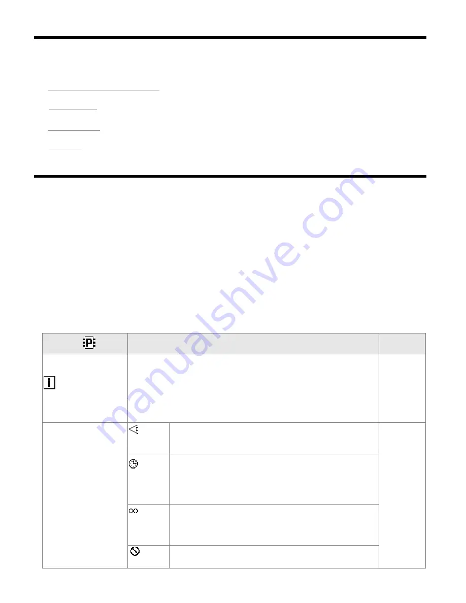
Table 12.4.3. The parameters in the 

Control and alarms options

 menu for the selected section (1

÷

12) of the program (1

÷ 

4) 

Parameter   


Range of variability of the parameter and description 

Factory 

settings 


Assigned and active 

outputs


the numbers (

1

÷

4

 or 

None

) are displayed of the control outputs to which the 

presented program is related (using the parameters 

Setpoint (SP) selection

and of the auxiliary outputs for the current section of the program (set with 
the 

Assignment of the control signal

 parameter for the outputs and the 

Selection of auxiliary output

 parameter for the section); a description of the 

parameters is given in chapter 12.4.1 and in this table; if the value is 

None

, the 

program is not used or the outputs are disabled. 

None


Stage type 


Gradient 
(PV/min) 

achievement of the 

Set point value SP

 with the set gradient 

(ramping) defined by the parameter 

Gradient (PV/min)

, the 

stage 

type

 field in the operation status has the value of 

PV/min


Gradient 
(PV/min) 

   Stage 

time after 
reaching of 
the SP 

the time countdown starts after the measured value reaches the 
band defined by the parameter 

Hysteresis and band for the start 

of the stage time

, the 

stage type

 field in the status shows 

PV->SP


(achievement of the 

Setpoint value SP

) or the remaining 

Stage 

time

 (in minutes or seconds when time<1 min.) 


Continuous 
(without a 
time limit) 

the 

stage type

 field in the status always has the value 

PV->SP


(achievement of the 

Setpoint value SP

), at the same time this is 

the last section of the program with constantly enabled control 

  End 

(stop) 

the last section of the program, control stopped, status field 

stage 

type

 = 

Stop


Summary of Contents for AR654

Page 1: ...IVERSAL FOUR CHANNEL CONTROLLER WITH PROCESS RECORDING AND ATIMER Version 1 0 1 2017 03 24 APAR SALES OFFICE 05 090 Raszyn ul Ga czy skiego 6 Tel 48 22 101 27 31 48 22 853 49 30 E mail automatyka apar...

Page 2: ...TOUCHSCREEN 10 11 DESCRIPTION OF DATA SHOWN ON THE LCD DISPLAY 12 11 1 UPPERAND LOWER DEVICE STATUS BAR 12 11 2 VIEW OFAMEASUREMENT GROUPAND CONTROL PARAMETERS CONTROL 13 11 3 VIEW OFAMEASUREMENT GRO...

Page 3: ...MODBUS RTU TCP 37 21 USER S NOTES 40 Please pay particular attention to the text marked with this sign The manufacturer reserves the right to make changes to the design and the software firmware of t...

Page 4: ...N to change the operating modes of the associated outputs control start stop selection of the day night setpoint value manual automatic mode for outputs the analogue outputs are logically connected to...

Page 5: ...d transducers current output depending on the version compensation of line resistance for resistance sensors automatic or permanent compensation of thermocouple cold tip temperature automatic or perma...

Page 6: ...e 200 620 C thermocouple E TC NiCr CuNi 25 850 C Pt1000 RTD 3 or 2 wire 200 620 C thermocouple N TC NiCrSi NiSi 35 1 300 C thermocouple J TC Fe CuNi 40 800 C current mA Rin 100 0 4 20 mA thermocouple...

Page 7: ...B s depending on the type of the memory RS485 MODBUS RTU protocol SLAVE speed 2 4 115 2 kbit s sign format 8N1 galvanic separation Ethernet type 100base T socket RJ45 data transfer up to 135 kB s depe...

Page 8: ...signals a measurement connections RTD TC mA V mV R INPUT1 INPUT4 the parameters configuration is described in chapter 12 3 a 1 connection of the 2 and 3 wire transducer Iou output current Uou output...

Page 9: ...site In the Windows 7 system from the Device Manager level manual installation is performed in the following manner 1 Right click the item Apar Composite Device and select Update the driver software a...

Page 10: ...guration display of current measurement data as well as the date and the time configuration of the real time clock RTC and other parameters such as types measurement inputs names of measurement channe...

Page 11: ...ling the Device status screen hardware information operation and Ethernet services parameters current record number in the csv archive file etc the function is available also from the level of the F b...

Page 12: ...ching the area of the displayed measured value PV or setpoint value SP change of the setpoint value selected with the Setpoint SP selection parameter chapter 12 4 1 limit of settings defined by parame...

Page 13: ...iew of a measurement group text and an analogue indicator none single measurement chart Quick configuration screen for main parameters of the control channel 9 Tx Rx signalling of presence of serial t...

Page 14: ...haracters and unit up to 4 characters of the measurement channel name and unit taken from the AR654 txt file chapter 12 2 measured value PV with signalling of exceeded measurement range chapters 12 3...

Page 15: ...easured value PV and unit of the measurement channel chapters 11 2 and 11 3 graphic presentation of the measurement analogue indicator works in the range set by the parameters Bottom of the range for...

Page 16: ...ter to be changed viewed use the SET button or touch the selected item in the menu also in order to edit the parameter use the UP DOWN LEFT or RIGHT button or the scroll bar to change the value of the...

Page 17: ...eypad or on line via the computer s USB port because the changed parameter values are stored in the internal memory after the user exits the Main Menu by pressing the ESC button or disconnects the dev...

Page 18: ...2 IN3 IN4 The smallest of the measurements IN3 and IN4 Sum of the measurements IN1 IN2 The smallest of the measurements IN1 IN2 and IN3 Sum of the measurements IN3 IN4 The smallest of IN1 IN2 IN3 IN4...

Page 19: ...signal 0 10 V 0 60 mV voltage signal 0 60 mV 0 850 resistance signal 0 850 Line resistance 1 0 00 50 00 total resistance of leads for 2 wire RTD sensors and 850 0 00 Thermocouple cold tip temperature...

Page 20: ...For outputs that are not related to any displayed measurement channels the Quick configuration screen chapter 11 7 is not available and the operating parameters of those outputs must be configured in...

Page 21: ...arameters Setpoint value for the manual mode and Pulsing period for the manual mode described further in this table Setpoint value SP selection Setpoint alarm value SP1 applies to SP1 and H1 from the...

Page 22: ...ter is insignificant chapter 12 4 1 3 5 sec Output emergency state No change status of the control alarm outputs if the measurement range of the control signal is exceeded or in the case of a failure...

Page 23: ...ement channel is to use the Quick configuration screen chapter 11 7 As an alternative it is possible to change the setpoint values in the parameter configuration mode using the methods described in ch...

Page 24: ...program control chapter 12 4 3 which can be useful to control the actuator elements e g heating cooling with power control or for impulse optical acoustic signalling The operation status and the setp...

Page 25: ...nu for the selected PID set 1 8 Parameter Range of variability of the parameter and description Default settings Assigned and active outputs the numbers 1 4 or None are displayed of the control output...

Page 26: ...location of the range of proportionality Pb in relation to the setpoint value SP for heating parameter Control type Reverse heating b location of the range of proportionality Pb in relation to the se...

Page 27: ...used buttons or BIN inputs The power supply must be switched on immediately after the tuning is started in the output switch on delay phase If the power supply is switched on later an erroneous analy...

Page 28: ...2 and in the Quick configuration screen the status of operation of the program is shown in the line starting with the phrase PRGx where x is the number of the program the meaning of the individual fie...

Page 29: ...and the Pulsing period taken from the parameters of the associated auxiliary output chapter and table 12 4 1 Sound signal Disabled signalling of the duration of the section with a built in acoustic tr...

Page 30: ...active within the range of the Time defined by the parameters Start and End of time limit Above the permission threshold recording is active when the measured value defined by the Selection of permis...

Page 31: ...ected or the internal memory when there is no USB memory Identification number ID 0 999 an individual device number entered into the initial records in the archive file csv in order to distinguish arc...

Page 32: ...e names as well as access to the archive files with the exception of the RS485 Moreover the Ethernet enables displaying information on the operating status and on measurements of the controller in any...

Page 33: ...hout a fixed public IP address an active account in a DDNS service is required the description can be found in chapter 12 8 1 Disabled Enabled Dynamic DNS settings and status Configuration data and st...

Page 34: ...ary unavailability of the service or permanent nature which indicates inadequate Internet connection improper configuration of the connection or service codes 2 to 12 e g DDNS 5 means invalid username...

Page 35: ...switched on the control status is exactly the same as at the time of switching off the power supply no change chapter 12 6 Touch panel lock touch screen and keypad lock except for F BIN5 input functi...

Page 36: ...tes text files with the csv extension in the internal memory or the USB memory Additional new csv files are created each time the power supply is switched on and each time a new recording is started e...

Page 37: ...disk operations being performed In order to close the message window appearing in the display use the SET or ESC button Fig 15 Appearance of an example message window 16 IMPORTANT COMMENTS PERTAINING...

Page 38: ...both ends of the line 150 each between lines Equipment from different manufacturers that form the RS485 network e g RS485 converters USB may have integrated polarizing and terminating resistors in su...

Page 39: ...unctions READ 3 or 4 WRITE 6 Table 19 1 Request frame format of the MODBUS TCP protocol for the READ and WRITE functions frame length 12B Heading of the MODBUS protocol 7 bytes Function code READ or W...

Page 40: ...reserved R 0x42 66 0x0101 0x630C years HB and months LB Parameter Start of the time limit chapter 12 5 R W 0x43 67 0x0100 0x1F17 days HB and hours LB R W 0x44 68 0x0000 0x3B3B minutes HB and seconds...

Page 41: ...2 Parameter State of control after power up R W 0xAA WY 32 0 2 Parameter Control time R W 0xAB WY 32 0x0101 0x630C years HB and months LB Parameter Start of control time R W 0xAC WY 32 0x0100 0x1F17...

Page 42: ...R W 0x14E 334 0x0000 0xFFFF Octet2 HB Octet1 LB 0x14F 335 0x0000 0xFFFF Octet4 HB Octet3 LB Parameter Default gateway chapter 12 8 R W 0x150 336 0x0000 0xFFFF Octet2 HB Octet1 LB 0x151 337 0x0000 0xFF...

Reviews: