


17
- make sure that the serial port drivers have been installed correctly (chapter 8)
- disconnect for a few seconds and then reconnect the controller to the USB port
- restart the computer
3.
From the configuration file created in the ARSOFT-CFG-WZ1 software or copied from another controller of the
same type to copy the configuration,
off-line configuration
:
- in ARSOFT-CFG-WZ1 set the required parameters (except for the
RTC
and the identification number
ID
)
- a current configuration can also be prepared by modifying the values read from the existing files
- save the created configuration in an
AR654.cfg
or
AR654.txt
file and save it in a USB memory
- in the
Memory and file options
of the controller, import the configuration from the USB memory, chapter 12.6.
- after the configuration has been completed, the memory can be disconnected from the USB socket
As an alternative to the configuration methods described above, the user can prepare his own application using
the available serial interfaces and the MODBUS-RTU or MODBUS-TCP communication protocol.
In the event of differences between the indications and the actual value of the input signal, the zero and the
sensitivity of a sensor can be adjusted in the
Measurement inputs configuration
menu: the
Offset calibration
and
the
Slope calibration
(sensitivity) parameters, chapter 12.3.
In order to restore the factory settings, the
Restore default
file action can be used, which is described in chapter 12.6.
NOTE:
!
Do not shut down the power supply during the configuration performed using the keypad or on-line (via the
computer's USB port) because the changed parameter values are stored in the internal memory after the user exits
the
Main Menu
(by pressing the
[ESC] button)
or disconnects the device from the USB socket.
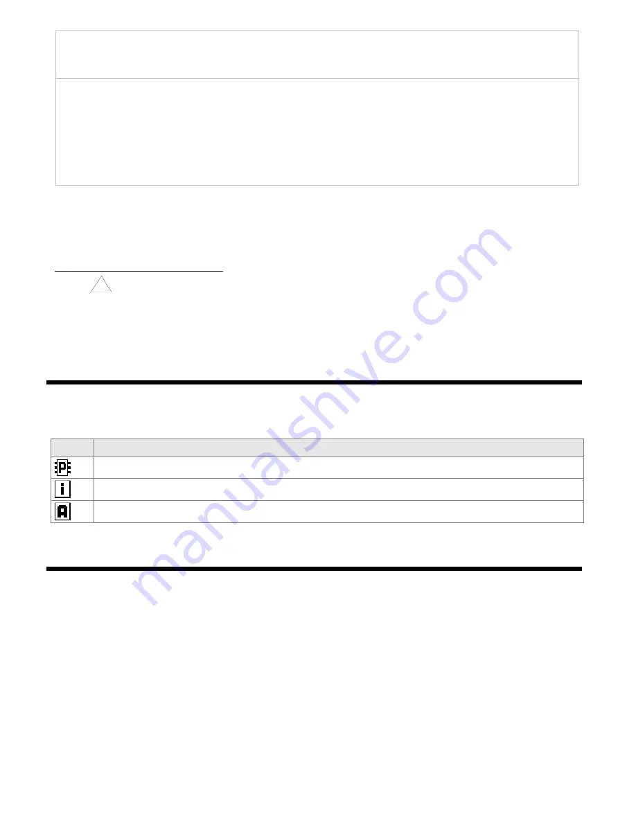
12.1. MEANING OF ICONS IN THE MENU ITEMS
In order to improve the ease of use and configuration of the device, additional graphic descriptive elements were
added to the menu in the form of icons (pictograms).
The shared meaning of some icons described the type of menu item is the following:
12.2. CONFIGURATION OF MEASUREMENT CHANNELS OF THE DISPLAY
The controller has 4 measurement channels to present the measured values on the display.
The measured values
can be directly the measurements from inputs 1÷4 or their mathematical formulas, such as difference, average,
sum, larger or smaller than, or ratio of the measurements. The measurement channels, together with the assigned
and switched on control and retransmission outputs, form control channels that are shown on the screen, for
which
Quick configuration screens
are also available (chapter 11.7) for the basic control/alarm parameters
(setpoint values
SP
, Start/Stop, etc.). If there are no related outputs, the message
STOP, no output
is displayed in
the control status and the message “
------
” is displayed in the field of the
SP
and
MV
values (if they are present in
the specific view, chapter 11). The method of assignment and configuration of the control and retransmission
outputs is described in detail in chapter 12.4.
Icon
Type of menu item (parameter)
parameter that can be modified using the buttons and the touch screen, saved in the internal memory
informative item, not modified directly using the buttons and the touch screen
file or disk action (operation) (chapter 12.6)


