background image

FBL2360 Brushless DC Motor Controller Datasheet 

11

RS485 Communication

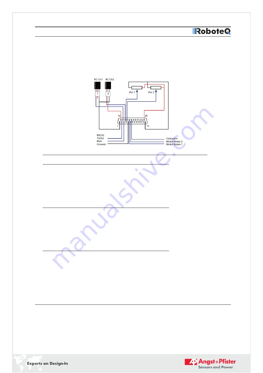
how to connect two outputs to motor brake solenoids and another output to an external 
status LED. You may omit any connection that is not required in your application. The 
controller automatically arbitrates the command priorities depending on the presence of a 
valid command signal in the following order: 1-RS232, 2-RC Pulse, 3-None. If needed, use 
the PC Utility to change the pin assignments and the command priority order.

FIGURE 10. Factory default pins assignment

Enabling Analog Commands

For safety reasons, the Analog command mode is disabled by default. To enable the 
Analog mode, use the PC utility and set Analog in Command Priority 2 or 3 (leave Serial as 
priority 1). Note that by default the additional securities are enabled and will prevent the 
motor from starting unless the potentiometer is centered, or if the voltage is below 0.25V 
or above 4.75V. The drawing shows suggested assignment of Pot 1 to ANA1 and Pot 2 to 
ANA4. Use the PC utility to enable and assign analog inputs.

USB Communication

Use USB only for configuration, monitoring and troubleshooting. USB is not a 
reliable communication method when used in an electrically noisy environments and 
communication will not always recover after it is lost without unplugging and replugging 
the connector, or restarting the controller. Always prefer RS232 communication when 
interfacing to a computer. USB and CAN can operate at the same time on the FBL2360. 
Plugging USB to a computer will not disable CAN interface.

RS485 Communication

RS485 is an industry standard for defining serial communication. Due to its balanced 
signalling, RS485 is effective over distances, even if other electrical signals are present. 
Its stability makes it well suited to connect multiple receivers to a single network.
You can operate RS485 in half-duplex mode and it is well suited for use with the Modbus 
protocol. On the 25-pin connector, RS485+ and RS485- pins are present.

11

FBL2360_1691-21588-0001-D-0720

Summary of Contents for RoboteQ FBL2360A

Page 1: ...ammed in the field with the latest features by downloading new operating software from Roboteq Applications Automatic Guided Vehicles Small Electric Vehicles Electric Bikes Terrestrial and Underwater...

Page 2: ...nsors analog or pulse frequency feedback Torque mode PID control loop Built in Battery Voltage and Temperature sensors Optional backup power input for powering safely the controller if the main motor...

Page 3: ...er hardware failure The user must assume that such failures can occur and must make his her system safe in all conditions Roboteq will not be liable in case of damage or injury as a result of product...

Page 4: ...a safe and trouble free operation All connections shown as thick black lines line are mandatory The controller must be powered On Off using switch SW1on the PwrCtrl tab Use a suitable high current fus...

Page 5: ...controller s bottom plate to a wire connected to the Earth while the charger is plugged in the AC main or if the controller is powered by an AC power supply Note 6 Beware not to create a path from th...

Page 6: ...f and battery current of 1A or more is measured for more than 0 5s This circuit will not protect against other sources of failure such as those described in the Important Safety Disclaimer on page 3 C...

Page 7: ...ode the FBL2360 and FBL2360S models can use motors equipped with absolute angle sensors with SPI interface such as found on the BL167 or BL90 motors from Micromotor When enabled the SPI signals are fo...

Page 8: ...sensor is captured on separate input pins The SSI Encoder is only featured on A T and E versions of Roboteq products TABLE 3 Pin Number 1 2 3 4 5 Row 1 5V CLK Data 2 Data 1 GND Row 2 5V Clock Data 2...

Page 9: ...ignal Pin Number Pin Name Sin1 9 ASIN1 Cos1 10 ACOS1 Sin2 24 ANA7 ASIN2 Cos2 12 ANA8 ACOS2 Exc 17 ANA4 EXC GND 1 5 or 13 GND Commands and I O Connections Connection to RC Radio Microcomputer Joystick...

Page 10: ...ENC1B Unused 25 5VOut 13 GND Note 1 Analog command is disabled in factory default configuration Note 2 STO functionality only available in T versions See STO section for details Note 3 Pulse input en...

Page 11: ...low 0 25V or above 4 75V The drawing shows suggested assignment of Pot 1 to ANA1 and Pot 2 to ANA4 Use the PC utility to enable and assign analog inputs USB Communication Use USB only for configuratio...

Page 12: ...oller with the PC utility Battery Backed Clock and Variables The battery backed clock and variables feature allows accurate time date stamping of information such as status and error reports It is imp...

Page 13: ...enabled two digital inputs DIN1 and DIN2 are remapped as STO1 and STO2 The inputs are redundant and both must have a 6V to 30V signal present at the same time in order for the Power MOSFETs to be ener...

Page 14: ...onsider using Positive Lock connectors from TE Connectivity or their equivalent These connectors have a spring loaded tab latch pin that will lock into the hole of the male tab Electrical Specificatio...

Page 15: ...Motor current All 1 500 8 65000 msec Short Circuit Detection threshold 9 Between Motor wires or Between Motor wires and ground or Between Motor wires and Vmot FBL2360 125 10 Amps FBL2360S 250 10 Amps...

Page 16: ...Level Ground to Input pins 3 30 Volts Analog Input Range Ground to Input pins 0 5 1 Volts Analog Input Precision Ground to Input pins 0 5 Analog Input Resolution Ground to Input pins 1 mV Encoder Fre...

Page 17: ...dity Case 95 Ambient temperature Ambient 55 o C Pollution Degree Fast fuse to install 3 FBL2360 4 40 2 x 40 Amps FBL2360S 4 2 x 40 Amps Overload motor protection Check note 5 Note 1 Thermal protection...

Page 18: ...ure 20 55 C STO Storage temperature 20 70 C Humidity 5 95 IP degree IP40 Operating Altitude 2000 m Cable Length 2 m EMC Immunity According to IEC 61800 3 and IEC 61800 5 2 Annex E CE Declaration Avail...

Page 19: ...B Connector LEDs 5 50 139 7mm 5 50 139 7mm 3 00 76 2mm 1 25 31 8mm 0 24 6 0mm 5 00 127 0mm FIGURE 15 FBL2360 top view and dimensions Revision Date Additions Changes 1 1 April 23 2019 Added T version w...

Page 20: ...hristian Mohrenstecher Phone 41 76 444 57 93 christian mohrenstecher angst pfister com Pressure Sensors Load Cells Philipp Kistler Phone 41 44 877 35 03 philipp kistler angst pfister com Power supplie...

Reviews: