August 2012
L010796
7
Motor Selection
The DPE25611 incorporates a Bipolar Microstep Driver that is compatible with both Bipolar and
Unipolar Motor Configurations, (i.e. 8 and 4 lead motors, and 6 lead center tapped motors).
Step motors with low current ratings and high inductance will perform better at low speeds, pro-
viding higher low-end torque. Motors with high current ratings and low inductance will perform
better at higher speeds, providing more high-end torque.
Since the DPE25611 is a constant current source, it is not necessary to use a motor that is rated
at the same voltage as the supply voltage. What is important is that the driver is set to the ap-
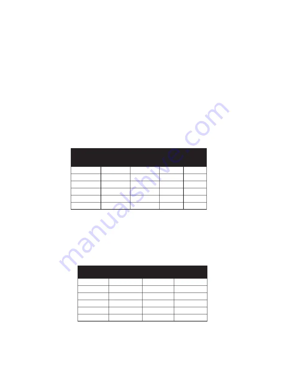
propriate current level based on the motor being used. Refer to the following chart for setting the
current potentiometer based on the current code in the part number of the motor. Examples of
motor part numbers are shown below. Anaheim Automation offers a comprehensive line of step
motors in 14, 17, 23, 34 and 42 frame sizes. Contact the factory to verify motor compatibility
with the DPE25611.
Section 2: Driver Functions
Step Motor Current Setting Guide
Unipolar
Rating
Series Peak
Rating
Parallel
Peak Rating
Series
Current
Setting
Parallel
Current
Setting
0.5A
0.5A
1.0A
0%
25%
1.0A
1.0A
2.0A
25%
75%
1.5A
1.5A
3.0A
50%
100%
2.0A
2.0A
4.0A
75%
100%
2.5A
2.5A
5.0A
100%
----
3.0A
3.0A
6.0A
100%
----
Anaheim Automation offers motor cable, making hook-ups quick
and easy! Contact the factory or visit our website for more motor
and cable offerings.
Setting the Output Current
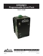
The output current on the DPE25611 is set by an onboard potentiometer. This potentiometer
determines the per phase peak output current of the driver. The relationship between the output
current and the potentiometer value is as follows.
Peak Current Potentiometer
Setting
Peak Current Potentiometer
Setting
0.50A
0%
1.70A
60%
0.70A
10%
1.90A
70%
0.90A
20%
2.10A
80%
1.10A
30%
2.30A
90%
1.30A
40%
2.50A
100%
1.50A
50%
---
---
Refer to Table 5 for specific motor current settings.
July 2018


