background image

I n s t r u c t i o n   M a n u a l

D X L i n k

  F i b e r   T r a n s m i t t e r s / R e c e i v e r s
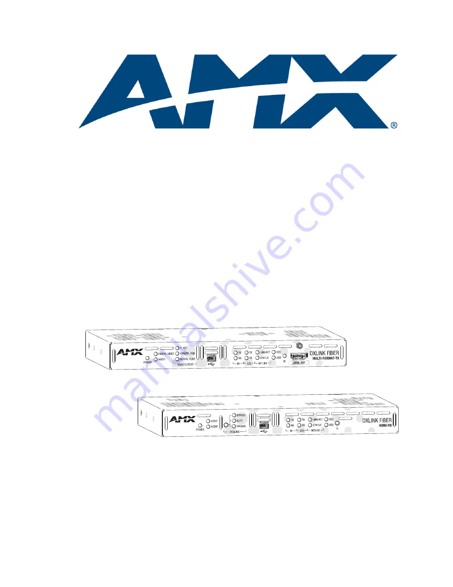
DXLink

 Fiber Transmitters and Receivers

DXF-TX-MMD and DXF-RX-MMD

DXF-TX-SMD and DXF-RX-SMD

 DXF-TX-MMS and DXF-RX-MMS

DXF-TX-SMS and DXF-RX-SMS

R E V   B :   1 1 / 1 9 / 1 4

Summary of Contents for DXF-RX-MMD

Page 1: ...ction Manual DXLink Fiber Transmitters Receivers DXLink Fiber Transmitters and Receivers DXF TX MMD and DXF RX MMD DXF TX SMD and DXF RX SMD DXF TX MMS and DXF RX MMS DXF TX SMS and DXF RX SMS REV B 11 19 14 ...

Page 2: ... switch on and off any load that is properly connected to our lighting Products as long as the AMX lighting Products are under warranty AMX also warrants the control of dimmable loads that are properly connected to our lighting Products The dimming performance or quality thereof is not warranted due to the random combinations of dimmers lamps and ballasts or transformers d AMX software and firmwar...

Page 3: ...cifications DXLink Fiber Transmitters and Receivers 32 Installation and Setup 38 Site Recommendations 38 General Hazard Precautions 38 Setup Information 39 DXLink Fiber TX Attaching Signal Transport and Control Cables 51 DXLink Fiber TX Applying Power 53 DXLink Fiber RX Attaching Signal Transport and Control Cables 53 DXLink Fiber RX Applying Power 55 Duplex Hardware Directional Mode Configuration...

Page 4: ...D_COMMANDs 79 DXLink Fiber Receiver Audio SEND_COMMANDs 81 DXLink Fiber Transmitter Video SEND_COMMANDs 82 DXLink Fiber Transmitter Audio SEND_COMMANDs 86 IR SEND_COMMANDs 87 Serial SEND_COMMANDs 91 DXLink Fiber Transmitter USB SEND_COMMANDs 93 DXLink Fiber Receiver USB SEND_COMMANDs 93 Common DXLink Fiber TX RX SEND_COMMANDs 94 DXLink Fiber System SEND_COMMANDs 95 SEND_STRING Escape Sequences 96 ...

Page 5: ...r 125 Appendix D Cable Details and Pinout Info 127 Overview 127 HDMI Connector Cable Pinout 127 HD 15 Connector Cable Pinout 128 DVI Pinout for DVI to HDMI Cable 129 Appendix E Supported Input Resolutions 130 Available Pixel Display and Refresh Rate 130 Appendix F Supported Output Resolutions 133 HDMI and DVI Supported Output Resolutions 133 Digital Video Output Resolution Support 134 Appendix G F...

Page 6: ...e smocks and conductive work mats are specifically designed for this purpose Anyone performing field maintenance on AMX DXLink Fiber equipment should use an appropriate ESD field service kit complete with at least a dissipative work mat with a ground cord and a UL listed adjustable wrist strap with another ground cord These items should not be manufactured locally since they are generally composed...

Page 7: ...oming from your AMX product turn it off immediately and call technical support For products with multiple power supplies in each unit make sure all power supplies are turned on simultaneously Use surge protectors and or AC line conditioners when powering AMX products Only use a fuse s with the correct fuse rating in your enclosure Make sure the power outlet is close to the product and easily acces...

Page 8: ...e que tous les blocs d alimentation des appareils dotés de blocs d alimentation multiples dans chaque unité soient allumés simultanément Servez vous de protecteurs de surtension ou de conditionneurs de lignes à courant alternatif lorsque vous mettez les appareils AMX sous tension Placez uniquement des fusibles de calibre exact dans les boîtiers Veillez à ce que la prise de courant soit proche de l...

Page 9: ...for a Class A digital device pursuant to part 15 of the FCC Rules These limits are designed to provide reasonable protection against harmful interference when the equipment is operated in a commercial environment This equipment generates uses and can radiate radio frequency energy and if not installed and used in accordance with the instruction manual may cause harmful interference to radio commun...

Page 10: ...the purposes of this definition submitted means any form of electronic verbal or written communication sent to the Licensor or its representatives including but not limited to communication on electronic mailing lists source code control systems and issue tracking systems that are managed by or on behalf of the Licensor for the purpose of discussing and improving the Work but excluding communicati...

Page 11: ...NFRINGEMENT MERCHANTABILITY or FITNESS FOR A PARTICULAR PURPOSE You are solely responsible for determining the appropriateness of using or redistributing the Work and assume any risks associated with Your exercise of permissions under this License 8 Limitation of Liability In no event and under no legal theory whether in tort including negligence contract or otherwise unless required by applicable...

Page 12: ... DXLink Fiber Transmitters and Receivers Duplex DXLink Fiber Transmitter and Receivers Simplex On the rear of all Transmitter units the number will be FG1010 36X indicating they share a common metal box design On the rear of all Receiver units the number will be FG1010 56X indicating they share a common metal box design The multimode and single mode fiber optic transceivers allow for in the field ...

Page 13: ...mmunication data via its RX to the destination device If needed communication data from the destination device can return to the Master for processing via the same path Bidirectional is the default Directional Mode for DXLink Fiber Duplex units if both fiber strands are connected Setting DIP switch 4 to ON enables Unidirectional Mode see below and the lack of a return fiber path results in the uni...

Page 14: ...iber units are designed for transmission of an HDMI signal over fiber optic cable DXLink Fiber Duplex multimode and single mode transceivers support bidirectional communication Bidirectional Mode or unidirectional communication Unidirectional and Data Link lost Mode DXLink Fiber Simplex multimode and single mode transceivers only support unidirectional communication Bidirectional Mode Communicatio...

Page 15: ...mparative shorter distance optical runs than the single mode cable Single Mode SFP Fiber Optic Transceiver Single mode SFP fiber optic transceivers are used in the DXLink Fiber units specified in the table at the top of the previous page Depending on the transceiver model it will have a bright blue latch or a blue label on the latch top with white triangles showing data flow direction The single m...

Page 16: ...Transmitters have IR ports which also send data via the fiber optic cable Configuration of Ethernet IR RS 232 and USB for units in Unidirectional or Data Link lost Mode requires additional information found in Unidirectional Mode LAN Configuration on page 60 DXLink Fiber HDMI Receivers The DXLink Fiber Receivers feature SmartScale Technology integrated EDID output scaling to ensure an appropriate ...

Page 17: ...oDetect on the Transmitters and SmartScale on the Receivers work to automatically recognize any device s supported resolutions and signal type parameters allowing switching out source and destination devices without manual setup Also included is the ability to control detailed timing parameters for customized video output formats SmartScale is the ability to configure the scaling output by automat...

Page 18: ...lications DXLink Fiber Transmitters and Receivers Duplex and Simplex are ideal for any sources and destinations designed into Enova DGX integrated systems that require the distance capabilities and or inherent security of fiber with bidirectional or unidirectional data transfer These transmitters and receivers easily handle campus wide distribution of sources that are shared between classrooms in ...

Page 19: ...ideo present through the unit composite or Y C Y Pb Pr or RGB RGBHV or RGBS Program port This port USB mini B connector supports DGX Configuration Software for programming a custom VGA or HDMI EDID IR LEDs TX and RX LEDs indicate active IR communication 232 LEDs RS 232 serial TX and RX LEDs indicate active serial communication for details see page 57 NetLinx LEDs Link Act LED indicates network com...

Page 20: ...ideo that is present through the system DXLink Fiber TXs Indicator LEDs on the Front LED Normal Display Indicates Power Green Power is applied to the unit Digital Video Green A digital video signal is present through the unit Audio Digital Green Embedded audio signal is present through the unit Analog Video One of the 3 LEDs will be Green The type of analog video present through the unit C composi...

Page 21: ...ing capability The HDMI connector also supports a DVI D signal with the use of a DVI to HDMI cable Note When a digital video source cable is plugged into the HDMI connector the Digital Video LED on the front of the TX and the Video LED on the Receiver connected directly or via the switcher turn green to show that video is present through the system Stereo Audio In Jack The Stereo Audio In jack is ...

Page 22: ...n to being directly connected to a device this port can be connected as an independent native NetLinx control port from a networked NetLinx Central Controller USB Port The USB mini A B Host port on the rear of the TX connects to a PC The Host port forwards HID keyboard and mouse data received from a directed DXLink Receiver s USB port the Receiver can be either Fiber or Twisted Pair In Bidirection...

Page 23: ...se the Scaling button to select one of the 3 scaling options Bypass Auto default or Manual For information on using the Scaling button and options for persisting the Scaling Mode see page 61 Program port This port will be supported in a future firmware upgrade IR LEDs TX and RX LEDs indicate active IR communication 232 RS 232 LEDs TX and RX LEDs indicate active serial communication for details see...

Page 24: ...ximum efficiency and savings Note Configuration of Ethernet IR RS 232 and USB for units in Unidirectional Mode or Data Link lost Mode requires additional information found in Unidirectional Mode LAN Configuration on page 60 DXLink Fiber RXs Indicator LEDs LED Normal Display Indicates Power Green Power is applied to the Receiver Video Green A video signal is present through the Receiver Audio Green...

Page 25: ...but must be instead transported via the ICS LAN 10 100 port see Unidirectional Mode LAN Configuration on page 60 IR RX Port The IR RX port is used for IR control see page 28 This port is a 3 5 mm stereo jack In addition to being directly connected to a device this port can be connected as an independent native NetLinx control port from a networked NetLinx Central Controller IR TX Port The IR TX po...

Page 26: ... setting the DIP switch toggles make sure any toggles that need to be ON are flipped toward the AMX sticker A four toggle DIP switch is on the bottom of the DXLink Fiber Transmitters and Receivers 1 Toggle is used for enabling disabling the physical ICS LAN 10 100 port page 44 2 Toggle is used for setting the DXLink Fiber units to either automatically or manually determine the DXLink Mode 3 Toggle...

Page 27: ...g one of the following methods By using a cable with a USB mini A plug to connect a USB hub to which a keyboard and mouse can be attached By connecting directly to a keyboard or mouse using the appropriate mini A plug adapter cable Note Configuration of USB HID in Unidirectional or Data Link lost Mode requires additional information found in Unidirectional Mode LAN Configuration on page 60 HID Dev...

Page 28: ...93 Note Configuration of USB HID in Unidirectional or Data Link lost Mode requires additional information found in Unidirectional Mode LAN Configuration on page 60 IR Control on DXLink Fiber Transmitters and Receivers Duplex Optional The following two items are required for IR control In addition a compatible remote control unit can be used with the system The two items listed are not included wit...

Page 29: ...tional Data Link lost Note An additional configuration is a mix of two Directional Modes in a single system For example a signal is sent from source to destination through individual runs of Bidirectional Mode and Unidirectional Mode joined by a switcher Directional Mode refers to the flow of signals and communication data within the system Bidirectional Mode When data flows in two directions the ...

Page 30: ...to communicate in either half or full duplex Ethernet Mode discovery and configuration information is available through Telnet commands For further information see Establishing a Terminal Connection Via Telnet on page 104 Master Connection Mode Master Connection Mode refers to the modes of communication used for connection to the Master as specified via the SET CONNECTION Telnet command Auto Mode ...

Page 31: ... on the DXLink Fiber RX with the Scaling button see page 61 or with SEND_COMMANDs see page 79 or through DGX Configuration Software when scaling is being done via an Enova DXLink Fiber Output Board Auto Mode Default Auto Mode SmartScale allows the destination device to choose the resolution it needs Manual Mode Manual Mode allows the user to configure the resolution the video will display through ...

Page 32: ... Power Connector 2 1 mm DC power jack Operational Temperature 32 F to 104 F 0 C to 40 C Storage Temperature 22 F to 158 F 30 C to 70 C Operational Humidity 5 to 85 RH non condensing Storage Humidity 0 to 90 RH non condensing Dimensions Depth Width Height 5 15 in 13 08 cm 8 71 in 22 12 cm 1 00 in 2 54 cm Weight Approximately 1 1 lb 0 5 kg Shipping Weight Approximately 2 2 lb 1 0 kg Mounting Options...

Page 33: ...t of front plate when fan is active Approvals UL 60950 1 CSA 60950 1 IEC 60950 1 CE EN 60950 1 CE EN 55022 Class A CE EN 55024 FCC CFR Title 47 Part 15 Subpart B Class A ICES 003 Class A RoHS WEEE Other AMX Equipment AMX Products Compatible with DXLink Fiber Transmitters Enova DGX Digital Media Switchers AMX Products Compatible with DXLink Fiber Receivers Enova DGX Digital Media Switchers Included...

Page 34: ...ed Pair Transmitter HDMI Specifications Compatible Formats HDMI HDCP DVI DVI requires conversion cable Signal Type Support HDMI DVI D Single Link via a DVI to HDMI cable adapter DisplayPort input only with HDMI or DVI cable adapter Video Data Rate max 4 95 Gbps 5 568 Gbps Video Pixel Clock max 165 MHz 185 625 MHz Progressive Resolution Support 480p up to 1920x1200 60 Hz supported resolutions are l...

Page 35: ...ration Software via the USB Program port on the TX For the specific EDID list see the specifications in the Enova DGX DXLink Fiber Boards chapter in the Instruction Manual Enova DGX 8 16 32 64 Digital Media Switchers Input Voltage nominal 1 0 Vpp differential Input Re clocking CDR Yes Input Equalization Yes adaptive Input Connector HDMI Type A female Local Loopback Output Connector HDMI Type A fem...

Page 36: ...put Resolutions appendix see page 130 Interlaced Resolution Support 480i 576i 1080i supported resolutions are shown in the Supported Input Resolutions appendix see page 130 Auto Adjust Input Supported RGB Input Signal Level Range 1 Vpp nominal RGB Input Impedance 75 Ω HV Sync Input Signal Level Range 2 to 5 Vpp HV Sync Input Impedance 2 5 pF typical 10 pF max Digital Processing 24 bit 165 MHz Y Pb...

Page 37: ...ample Rate 32 kHz 44 1 kHz 48 kHz 96 kHz S PDIF Input Signal Level Range 200 mVpp to 600 mVpp terminated S PDIF Input Impedance 75 Ω Analog to Digital Reference Level 2 5 dBu 0 dBfs Input Connector 3 5 mm mini stereo jack analog stereo RCA jack S PDIF DXLink Fiber RX Output Signal Types Stereo analog Analog Output Level max 2 5 dBu unbalanced 2k Ω load Analog Output Frequency Response 0 dB to 0 5 ...

Page 38: ...riction The DXLink Fiber units are designed to adequately dissipate the heat they produce under normal operating conditions however this design is defeated when high heat producing equipment is placed directly above or below them Important Do not place the unit in a confined space with no airflow thermal runaway can result and the unit will overheat Reliable Earthing Grounding Reliable earthing of...

Page 39: ...n be sent over the fiber optic cable Unidirectional Mode Ethernet IR RS 232 and USB HID keyboard and mouse data cannot be sent over the fiber optic cable This functionality can be provided in Unidirectional Mode by connecting the ICS LAN port to a network for details see Unidirectional Mode LAN Configuration on page 60 Endpoint Mode Standalone A standalone DXLink Fiber TX RX pair are connected dir...

Page 40: ...s stereo audio port In a system where DXLink Fiber Transmitters and Receivers are used in conjunction with an Enova DGX 8 16 32 64 the cable runs from a Transmitter to a DXLink Fiber Input Board and from a DXLink Fiber Output Board to a Receiver depend on whether the transceivers are single mode or multimode and on the quality of the cable see cable specifications on page 32 Tip For systems with s...

Page 41: ...ink Fiber TX Enova DGX Input Board Enova DGX Output Board DXLink Fiber RX Single Mode TX DXLink Fiber SM Input Board DXLink Fiber SM Output Board Single Mode RX Single Mode TX DXLink Fiber SM Input Board DXLink Fiber MM Output Board Multimode RX Single Mode TX DXLink Fiber SM Input Board Any board Not applicable Multimode TX DXLink Fiber MM Input Board DXLink Fiber MM Output Board Multimode RX Mul...

Page 42: ...standalone pair can also work together as an extender solution for transmission of HDMI over fiber cable The standalone setup supports DVI D signals with the use of a DVI to HDMI cable adapter A standalone TX RX pair can also support an analog video source The length of the cable runs depend on whether the transceivers are single mode or multimode and the quality of the cable see cable specificati...

Page 43: ...op was created when the Enova DGX 16 was connected to a LAN and one of its DXLink Fiber Duplex Transmitters in Bidirectional Mode was connected to the same LAN The Transmitter must be disconnected from the LAN The same problem would also occur if an enclosure and one or more of its DXLink Fiber Duplex Receivers in Bidirectional Mode were connected to a common LAN Remember to avoid network loops Im...

Page 44: ...e enable ICS LAN functionality see page 95 Tip Common setup scenarios and their DIP switch settings are provided in a table on page 46 1 Toggle Settings OFF default When the 1 Toggle is set to OFF network activity over the ICS LAN 10 100 port is disabled ON When the 1 Toggle is set to ON network activity over the ICS LAN 10 100 port is enabled Toggle 1 Set to ON When a Transmitter or Receiver is c...

Page 45: ...s require IR and or Serial control by a separate NetLinx Master then they need to be in Endpoint Mode Only one must be connected via the ICS LAN 10 100 port to the Master or to a LAN with the Master on it This requires 1 Toggle to be ON to enable the ICS LAN port 2 Toggle needs to be ON to place the units in Endpoint Mode if needed and 3 Toggle needs to be ON to enable network connectivity Note On...

Page 46: ...accordingly A detailed explanation of functions for each toggle is provided above and on the previous page Tip Each toggle s ON position is toward the connectors on the rear of the DXLink Fiber units see page 44 Connection requires Duplex hardware with both fibers connected and in Bidirectional Mode will not work in Unidirectional Mode Connect the ICS LAN 10 100 port on one of the DXLink Fiber uni...

Page 47: ...is only required on each unit if serial and or IR control is required from the Master Mounting Options for DXLink Fiber Units Rack Trays and Mounting Brackets The DXLink Fiber Transmitters and Receivers are classified as V Style modules which have optional V Style mounting hardware These versatile mounting options include rack trays and mounting brackets for desktops under desks on walls and on po...

Page 48: ...onality as well Fiber Optic Cable Wiring for Unidirectional Mode Simplex Default or Duplex Configurable When wiring fiber optic cable for secure unidirectional system capabilities a single fiber optic cable is used to wire from a DXLink Fiber Transmitter to a DXLink Fiber Input Board and another single fiber optic cable from a DXLink Fiber Output Board to a DXLink Fiber Receiver or directly from T...

Page 49: ...ink system When free run video is indicated video is not displayed nor is black video present out the endpoint RX This identifies a good connection with video flow between endpoints Transceiver LEDs in Unidirectional Mode Simplex Default or Duplex Configurable The following information applies to the LEDs above the fiber optic transceiver on Simplex or Duplex TXs RXs and boards in Unidirectional M...

Page 50: ...or LEDs The following information applies to the LEDs on the ICS LAN 10 100 RJ 45 connector on the units Link Activity L A Green LED On Link status is active when the Ethernet cable is connected and terminated correctly Off Link status is not active Speed Status SPD Yellow LED On Speed status is 100 Mbps Off Speed status is 10 Mbps FIG 18 Twisted pair cable pinouts for Ethernet connectors FIG 19 I...

Page 51: ...e to set the DIP switch s toggles if necessary see page 46 Tips for Fiber Optic Connections Keep dust plugs in transceivers until you are ready to make a connection Clean fiber optic cable ends before attaching to unit be sure to follow the cable manufacturer s instructions for inspecting and cleaning the cable ends Use gentle pressure when connecting fiber optic cables to transceivers normally an...

Page 52: ... stereo audio source into the Stereo Audio In jack For audio precedence information see page 51 DVI cable can be used instead via a DVI to HDMI cable adapter When cabling a simplex transceiver we recommend covering the unused port 6 ICS LAN 10 100 connector optional Attach a twisted pair cable from this connector to a LAN Note that the 1 Toggle on the DIP switch must be set to ON to enable this po...

Page 53: ...ic cables to transceivers normally an audible click is heard when the connector engages If unsure the connection is properly seated gently tug on the connector If fiber optic cables are removed from the transceivers reinsert dust plugs Multimode transceivers only If you are unsure that a multimode transceiver is passing a signal hold the unattached end of the fiber optic cable away from you and ta...

Page 54: ...rt For NetLinx programming information see page 77 4 USB port optional This port is for sending keyboard mouse commands to a PC You can either connect this port to a hub using a USB mini A cable and then connect keyboard and mouse to the hub or connect directly to a keyboard or mouse using the appropriate mini A plug adapter cable The port s default is enabled The USB LED on the front monitors thi...

Page 55: ...l display as stated in the table on the previous page Check all power connections Check the Detailed NetLinx Link Act and Status LED Behavior section on page 63 Try the suggestions in the Troubleshooting chapter page 97 For information on restoring the unit s default settings on power up see page 70 Caution The provided desktop power supply must be used to power the DXLink Fiber RX and it must not...

Page 56: ...default or in Data Link lost Mode see following note Note If the data return path is disconnected while the system is configured for Bidirectional Mode the system automatically drops into Data Link lost Mode To configure Duplex units for Unidirectional Mode 1 Ensure that the unit is not powered Disconnect power if necessary 2 Flip DIP switch 4 to the ON position enables Unidirectional Mode 3 Apply...

Page 57: ...ctional Mode with a setup that allows the units IR USB and serial communication via LAN when the system is in Endpoint Mode with an Enova Digital Media Switcher The Transmitter can either be Duplex configured for Unidirectional Mode or Simplex which can only support Unidirectional Mode In either case the fiber cable attached to the Transmitter has no data return path FIG 22 Serial data transfer an...

Page 58: ...e connector 2 Use the command RXON to enable this port on the Transmitter and the Receiver For complete Serial SEND_COMMAND programming information see page 91 Serial Control Endpoint Mode and SEND_COMMANDs With DXLink Fiber TX RX Duplex units connected to a switcher in Endpoint Mode serial operations in Bidirectional Mode are handled by the host providing control of the endpoints The Master s pro...

Page 59: ...inx IR Emitter cable FG10 000 11 to the IR TX port on the unit 2 Run the other end of the IR Emitter cable to the display device and locate the IR window 3 Attach the IR Emitter bud over the device s IR sensor by removing the cover on the reverse side of the Emitter and sticking the bud directly over the IR window Important When installation of the IR Receiver and IR Emitter is complete load the a...

Page 60: ...ee page 104 Unidirectional Mode LAN Configuration The only method for enabling IR RS 232 or USB in Unidirectional Mode with either Duplex or Simplex units requires connecting the system to a LAN since the Ethernet path via fiber which normally provides network support is not enabled Only one fiber is active and it only passes audio and video The following procedure applies to DXLink Fiber Duplex u...

Page 61: ...er the destination device without altering the signal s resolution Note Interlaced and progressive video are supported into the Transmitters the Receiver only supports progressive out unless it is in the Bypass Mode which is non scaling Auto Mode At power up the DXLink Fiber RX defaults to Auto Scaling unless a different Scaling Mode has been persisted In Auto Mode the DXLink Fiber RX uses the EDI...

Page 62: ...aling Mode from an attached RX and stores it in volatile memory The DXLink Output Board pushes the current Scaling Mode down to the DXLink Fiber RX if any of the following occurs 1 the RX is power cycled independent of the switcher 2 the RX is disconnected from the DXLink Output Board and then reconnected or 3 a different DXLink Fiber RX is connected to the DXLink Output board The DXLink Output Bo...

Page 63: ...N Normal Online with Master rest OFF ON Normal Boot DHCP found Note This state continues from the time an IP address is obtained until the device is online with the Master Fast blink then normal operation ON Normal Boot DHCP no server Note This state continues until a valid IP address is obtained OFF during light show then normal operation OFF until connected to Master Fast blink continues only du...

Page 64: ...put Board on one switching system determines that it is connected to a Duplex Input Board on another switching system the hardware will automatically disable all Ethernet and control on that connection port so that only audio and video signals are passed down the fiber optic cable On Simplex Boards Ethernet and control are always disabled When connecting switching systems via fiber optic transceiv...

Page 65: ... DHCP server device the DHCP connection is then propagated through the system s DXLink Fiber layer to the DXLink Fiber unit Important DHCP Mode will not function until the 3 Toggle on the DIP switch is set to ON see page 45 The 3 Toggle must be ON before the device is accessible via SEND_COMMANDs When in DHCP Mode the default setting the DXLink Fiber unit will attempt to get a DHCP lease consistin...

Page 66: ...an be used for initial network configuration of the units The default Telnet port is 23 Telnet is enabled by default A value of 0 disables the telnet server For details see Appendix B Telnet Terminal Commands on page 104 The appendix also includes a section on Master Connection Modes on page 119 If you set the Telnet port to 0 to disable it you will need to perform a factory reset using the ID Pus...

Page 67: ... If the Friendly Name is non blank both Friendly Name and Location are concatenated to make NDPSTRING2 otherwise NDPSTRING2 is generated from the unit s serial number Location blank Stored MAC Address of Master used for NDP binding 00 00 00 00 00 00 ICSP Device Number 0 0 receive dynamic device number from Master System Number 0 Telnet Port 23 A value of 0 disables the Telnet server Telnet is enab...

Page 68: ... state of a unit by its NetLinx LED behavior see page 71 Toggling Between IP Addressing Modes DHCP and Static IP DXLink Fiber Transmitters and Receivers support both DHCP and static IP addresses When the 3 Toggle is ON see page 45 the units automatically use DHCP with link local fallback However you can use a static IP address which has been set via a Telnet command SET IP or you can use the facto...

Page 69: ...nsmitter or Receiver 1 Check to be sure 3 Toggle on the bottom of the Transmitter or Receiver is set to ON 2 In NetLinx Studio s OnLine Tree select the Master to which the unit is bound 3 From the Diagnostic menu select Device Addressing The Device Addressing dialog box opens 4 In the ID Mode section enter the Device and System numbers that you want assigned to the device in the appropriate text b...

Page 70: ...tempt to come online if you release the ID Pushbutton prior to the faster blink rate 2 At the point that the blink rate increases release the ID Pushbutton 3 The Transmitter or Receiver will automatically reboot to complete the process Restore the Factory Firmware Image and Factory Default Parameters During power up if the ID Pushbutton is held until the Control NetLinx LEDs toggle back and forth ...

Page 71: ...D Status LED Boot with ID Pushbutton held down Slow blink 1 Hz Slow blink 1 Hz ID Pushbutton held down long enough for reset to default parameters Fast blink until ID Pushbutton is released then OFF Fast blink until ID Pushbutton is released then OFF ID Pushbutton held down long enough for reset to default firmware image Solid ON transitions to OFF once the unit completes writing to flash and is r...

Page 72: ...itcher the switcher s integrated Master is used for the IRL file transfer FIG 30 shows a Transmitter and a Receiver bound to the integrated Master in an Enova DGX 16 in NetLinx Studio s OnLine Tree Follow the instructions on the top of page 73 to prepare for IRL file transfer and the instructions on page 74 for the actual transfer FIG 30 NetLinx Studio Integrated Master Enova DGX 16 DXLink Fiber T...

Page 73: ...the switcher s integrated Master to the network e g from the LAN 100 1000 port on an Enova DGX 32 to a LAN b Verify that the target Transmitter or Receiver is connected via its fiber optic connection to a DXLink Fiber Input or Output Board respectively on the switcher c Verify that the switcher is powered on 5 Launch NetLinx Studio and open the OnLine Tree 6 Bind the target Transmitter or Receiver...

Page 74: ...age for IRL file transfers have been completed To send an IR Library IRL file to a Transmitter or Receiver 1 In NetLinx Studio select Tools File Transfer to open the File Transfer dialog box 2 Click Add to open the Select Files for File Transfer dialog box 3 Open the Other tab if the file you want to transfer is not included in the open workspace The Other tab consists of a display of the differen...

Page 75: ...ystem numbers for the selected device If the fields are populated Verify that the mapping information is correct for the selected device IRL files are sent to Port 3 IR Device Port on the Transmitter or Receiver Refer to the Device Numbering section on page 77 for information on device numbering for the Transmitter or Receiver If the device s assigned device number has been changed use the OnLine ...

Page 76: ...nsmitter or Receiver that the file is mapped to Additional Documentation For additional information on using NetLinx Studio refer to the WebConsole Programming Guide NX Series Controllers available at www amx com Additional IRL Information Unlike NetLinx NI Controllers ICSLan powered devices such as the DXLink Fiber Transmitter and Receiver units are not capable of having their IRL files received ...

Page 77: ...6 IR SEND_COMMANDs and CHANNELs page 87 SERIAL SEND_COMMANDs page 91 Transmitter USB SEND_COMMANDs page 93 Receiver USB SEND_COMMANDs page 93 Common DXLink Fiber Transmitter Receiver SEND_COMMANDs page 94 DXLink Fiber System SEND_COMMANDs page 95 SEND_STRING Escape Sequences page 96 Note For a list of all supported Telnet commands see page 106 Device Numbering and Ports Each DXLink Fiber unit has ...

Page 78: ...ing the product s current firmware version against the information in the Firmware Version table on page 102 FIG 31 NetLinx Studio OnLine Tree Ports 1 8 on DXLink Fiber Transmitter and Ports 1 7 on Receiver Ports 1 8 on DXLink Fiber Transmitter device number 01000 Port 1 Serial ICSP COM Port 2 Not used Port 3 IR Output Port 4 IR Input Port 5 USB HID input and output Port 6 Digital Video Audio Outp...

Page 79: ...ng Mode on the Receiver to AUTO SmartScale MANUAL or BYPASS Syntax SEND_COMMAND DEV VIDOUT_SCALE scaling mode Valid responses scaling mode AUTO MANUAL BYPASS Example SEND_COMMAND dvRX VIDOUT_SCALE MANUAL VIDOUT_RES_REF Requests the resolution and refresh rate of the video through the Receiver Note If the Scaling Mode is set to Bypass the response will be BYPASS Syntax SEND_COMMAND DEV VIDOUT_RES_R...

Page 80: ...ersion policy of the video through the Receiver to Stretch Maintain Zoom or Anamorphic For explanations of the ratio options see page 81 Syntax SEND_COMMAND DEV VIDOUT_ASPECT_RATIO ratio Valid responses ratio STRETCH MAINTAIN ZOOM ANAMORPHIC Example SEND_COMMAND dvRX VIDOUT_ASPECT_RATIO ZOOM VIDOUT_TESTPAT Requests the test pattern setting on the Receiver Syntax SEND_COMMAND DEV VIDOUT_TESTPAT Val...

Page 81: ...ttom of the display Zoom This aspect ratio conversion policy option maintains the input aspect ratio while zooming the image to fill the screen in all directions Image data may be lost on the top and bottom or to the left and right of the displayed image Anamorphic This aspect ratio conversion policy option is used with anamorphic formatted video sources so that the images appear correctly on the ...

Page 82: ... Syntax SEND_COMMAND DEV VIDIN_AUTO_SELECT ENABLE DISABLE ANALOG Valid responses value ENABLE DISABLE ANALOG Example SEND_COMMAND dvTX VIDIN_AUTO_SELECT ENABLE Note VIDIN_AUTO_SELECT must be set to DISABLE for a VIDIN_FORMAT command to take effect INPUT VIDEO Requests the video input being used on the Transmitter either the digital video Input 7 or the analog video Input 8 The output is always 6 I...

Page 83: ...OMPONENT S VIDEO COMPOSITE VGA Example SEND_COMMAND dvTX VIDIN_FORMAT COMPONENT Note VIDIN_AUTO_SELECT must be set to DISABLE for a VIDIN_FORMAT command to take effect VIDIN_RES_AUTO Requests the setting for the Auto mode on the Transmitter Enable or Disable Note Send to Port 8 Syntax SEND_COMMAND DEV VIDIN_RES_AUTO Example SEND_COMMAND dvTX VIDIN_RES_AUTO Returns a COMMAND of the form VIDIN_RES_A...

Page 84: ... Port 8 for analog video Syntax SEND_COMMAND DEV VIDIN_EDID Example SEND_COMMAND VIDEO_INPUT_1 VIDIN_EDID Returns a COMMAND of the form VIDIN_EDID source For the potential sources see the VIDIN_EDID command VIDIN_EDID Sets the EDID to be presented to the source on the video port addressed by the D P S Note For additional information on EDID management and the EDID variables used with this command ...

Page 85: ... video port Note After changing this setting it may be necessary to disconnect and re connect PC sources Syntax SEND_COMMAND DEV VIDIN_HDCP ENABLE DISABLE Example SEND_COMMAND dvTX VIDIN_HDCP ENABLE Enables the HDCP Compliance of the video input port 1 based on D P S VIDIN_VSHIFT Requests the vertical shift value of the analog video input port addressed by the D P S Important Send to Port 8 Syntax...

Page 86: ... a COMMAND of the form the value will be numerical ranging from 0 to 31 VIDIN_PHASE value VIDIN_PHASE Sets the input phase of the RGB video input port addressed by the D P S Important Send to Port 8 This command is valid only for inputs whose format is set to VGA Syntax SEND_COMMAND DEV VIDIN_PHASE value Valid responses value 0 31 Example SEND_COMMAND VIDEO_INPUT_1 VIDIN_PHASE 23 Audio SEND_COMMAN...

Page 87: ...EV AUDIN_FORMAT format Valid responses format HDMI SPDIF ANALOG Example SEND_COMMAND dvTX AUDIN_FORMAT ANALOG Important The order of precedence HDMI embedded audio S PDIF analog can be overridden with this command however you must first send AUDIN_FORMAT_AUTO DISABLE to disable the auto format function or the audio format will automatically switch back anytime the order of precedence is violated C...

Page 88: ... elapses CP Halt and clear all active or buffered IR commands and then send a single IR pulse Pulse and Wait times can be set with the CTON and CTOF commands Syntax SEND_COMMAND DEV CP code Valid responses code IR port s channel value 0 to 252 253 to 255 reserved Example SEND_COMMAND IR_1 CP 2 Clears the active buffered commands and pulses IR port s channel 2 CTOF Set the duration of the Off time ...

Page 89: ...IR port SET BAUD Use to set the IR communication parameters Note Before sending the SET BAUD command you must set the IR port to Data mode for the SET MODE command see next entry in table Note This value is not saved in non volatile memory and is reset to default 9600 N 8 1 at power up Syntax SEND_COMMAND DEV SET BAUD baud parity data stop Valid responses baud 9600 4800 2400 1200 600 300 150 parit...

Page 90: ...fault x x x enter SEND_COMMAND IR_1 XCH 3 Transmits the IR code as 3 enter SEND_COMMAND IR_1 XCH 34 Transmits the IR code as 3 4 enter SEND_COMMAND IR_1 XCH 343 Transmits the IR code as 3 4 3 enter Mode 1 Example x x x enter SEND_COMMAND IR_1 XCH 3 Transmits the IR code as 0 0 3 enter SEND_COMMAND IR_1 XCH 34 Transmits the IR code as 0 3 4 enter SEND_COMMAND IR_1 XCH 343 Transmits the IR code as 3...

Page 91: ...rt s communication parameters to 9 data bits and one stop bit CHARD Set the delay time between all transmitted characters to the value specified in 100 microsecond increments Syntax SEND_COMMAND DEV CHARD time Valid responses time 0 to 10000 1 second Example SEND_COMMAND dvRXRS232 CHARD 10 Sets a 1 millisecond delay between all transmitted characters CHARDM Set the delay time between all transmitt...

Page 92: ...END_COMMAND dvRXRS232 RXON Sets the RX RS 232 port to transmit received characters to the Master TXCLR Stop and clear all characters waiting in the transmit out buffer and stops transmission Syntax SEND_COMMAND DEV TXCLR Example SEND_COMMAND dvRXRS232 TXCLR Stops and clears all characters waiting in the RX serial port s transmit buffer SET BAUD shown in examples Or TSET BAUD Use either of these co...

Page 93: ...ple SEND_COMMAND dvTX USB_HID_SERVICE ENABLE Note This command persists through power cycling USB SEND COMMANDs Receiver Command Description USB_HID_ROUTE Requests the IP address or hostname of the host device Transmitter sending USB keyboard mouse data to the Receiver Syntax SEND_COMMAND DEV USB_HID_ROUTE Example SEND_COMMAND dvRX USB_HID_ROUTE Returns a COMMAND of the form USB_HID_ROUTE IP addre...

Page 94: ... port on DEVICE_1 Transmitters Disables all LEDs to the right of the Power LED on DEVICE_1 Note This parameter does not get stored in non volatile memory LEDs are enabled by default at each power up LED EN Receivers Enable all LEDs to the right of the Program port Transmitters Enable all LEDs to the right of the Power LED Syntax LED EN Example SEND_COMMAND DEVICE_1 LED EN Receivers Enables all LED...

Page 95: ...BLE PERSISTAV Receivers Persists the Scaler Mode resolution aspect ratio policy and audio output type to the DXLink Fiber Output Board Transmitters Disables the AUDIN_FORMAT_AUTO and persists the current audio format Syntax SEND_COMMAND DEV PERSISTAV Example SEND_COMMAND dvRX PERSISTAV FACTORYAV Receivers Clears the persisted settings for the Scaler Mode resolution aspect ratio policy and audio ou...

Page 96: ...fic device Syntax 27 17 time Valid responses time 1 to 255 measured in 100 microsecond increments Example SEND_STRING RS232_1 27 17 10 Sends a break character of 1 millisecond to the RS232_1 device 27 18 0 Clear the ninth data bit by setting it to 0 on all character transmissions Used in conjunction with the B9MON command see page 91 Syntax 27 18 0 Example SEND_STRING RS232_1 27 18 0 Sets the RS23...

Page 97: ...roblems by cabling direct without the DXLink Fiber units If using SEND_COMMANDs double check the command and the port number specified and re send the command see page 77 If any changes have been made try resetting the unit to the factory defaults see page 70 Additional Resources for Troubleshooting Switching Systems with DXLink Fiber Endpoints Enova DGX Digital Media Switcher We suggest checking ...

Page 98: ...xpected behavior Yellow LED fast blink unencrypted video present Yellow LED slow blink free run video present Yellow LED solid HDCP video present Green LED solid full bidirectional link established Green LED off link not established Green LED blinking Data Link lost Mode no Ethernet RS 232 IR or USB If Bidirectional Mode is required check return fiber path for proper connections and make sure DIP ...

Page 99: ...t the DIP switches to configure the DXLink Fiber unit for the specific type of system setup being used see the Common Scenarios tables on page 46 and page 47 Note If you cannot locate the DXLink Fiber unit in the Online Tree you can reset the factory default by holding the ID button during power up until the LEDs blink in unison and then releasing the ID button This will revert the DXLink Fiber un...

Page 100: ...When a Transmitter and or a Receiver are being used in conjunction with a switcher the switcher s integrated Master is used for the KIT file transfer FIG 32 shows a Transmitter and a Receiver bound to the integrated Master in an Enova DGX 16 in NetLinx Studio s OnLine Tree Follow the instructions on the top of page 101 to prepare for KIT file transfer and the instructions on page 103 for the actua...

Page 101: ...hat an Ethernet RJ 45 cable is connected from the switcher s integrated Master to the network e g from the LAN 100 1000 port on an Enova DGX 32 to a LAN b Verify that the target DXLink Fiber Transmitter or Receiver is connected via its fiber optic transceiver to a DXLink Fiber Input or Output Board respectively on the switcher c Verify that the switcher is powered on 4 Launch NetLinx Studio and op...

Page 102: ...ails on version differences see the applicable Readme file Caution Upgrading the firmware is a serious action in that if the upgrade fails it can leave the system completely non operational Caution If the application signals a failure you must immediately reboot the Transmitter or Receiver and attempt to upgrade the firmware again as the unit is in an unknown state and cannot be guaranteed to be o...

Page 103: ...accuracy before you send 6 Click Send to upgrade the firmware on the DXLink Fiber Transmitter or Receiver The Power LED blinks during the process for upgrading the firmware this is normal The progress of the upgrade displays in the Upload Status field Status is also indicated in the Status bar at the bottom The success of the upgrade or any errors that occur will be reported If an incorrect file h...

Page 104: ...ser credentials are required Enter username admin Enter protected password Welcome to DXF RX xxD v1 0 6 Copyright AMX LLC 2014 Note When security is enabled a user can retry logging in three times before being disconnected for information on setting a username and password see page 106 To establish a terminal connection via Telnet at the CMD prompt 1 From your Windows Taskbar at far left select St...

Page 105: ...et prompting for a user login Password Setting the Password will cause Telnet to prompt for a user login whether the username has been defined or not If the username has been defined this value must be entered However since the password can be set independently of the username it s possible to have a password defined but the username still at its default blank empty string In this case do not ente...

Page 106: ... a new Telnet username enter a username and press Enter b The program will indicate that the username is being stored 3 Type Set Telnet Password and press Enter a The program will prompt you to enter a password press Enter twice to clear both the Telnet username and password b Enter a password and press Enter c The program will prompt you to re enter the password re enter the password and press En...

Page 107: ...plies only to the Receiver Shows audio signal status Example audio Audio Output Analog Audio ON HDMI Audio ON Audio Mute OFF Audio Input N Value 0x00 0x17 0xFF Channel Status Bits Audio Type LPCM Dolby TrueHD DTS Master No Sampling Freq 44 1kHz Channel 0 Raw Data 0x00 0x00 0x00 0x30 0x73 Audio InfoFrames Channel 2 Raw Data 0x84 0x00 0x00 0x7C 0x01 0x00 0x00 0x00 0x00 0x00 0x00 0x00 0x00 0x00 AVI N...

Page 108: ...Int Level 6 0 Supported data types UByte UInt Level 7 0 Supported data types UByte UInt Level 8 0 Supported data types UByte UInt DIPSWITCH Displays the current value for each of the DIP switch s four toggles Example dipswitch Board Switch Settings DIP Setting Description 1 ON Enable ICS LAN 2 OFF Manual DXLink mode 3 ON Enable Network 4 OFF Force unidirectional mode DNS LIST Displays list of DNS ...

Page 109: ...LF TX 2075028 Type DHCP IP Address 192 168 44 86 Subnet Mask 255 255 255 0 Gateway IP 192 168 44 2 MAC Address 00 0f 3c 00 55 04 DHCP Server 192 168 43 2 Lease Origin THU 01 09 2031 12 59 02 Lease Duration SUN 01 12 2031 12 59 02 259200 sec Lease Renew T1 SAT 01 11 2031 00 59 02 129600 sec Lease Rebind T2 SUN 01 12 2031 03 59 02 226800 sec DNS Servers Domain suffix amx internal Entry 1 192 168 40 ...

Page 110: ...RNET MODE Ethernet mode is auto Note See SET ETHERNET MODE on page 113 GET FRIENDLY Displays the device s friendly name for NDP Example GET FRIENDLY name GET IP Displays the IP configuration of a device The device displays its D P S Host Name Type DHCP or Static IP Address Subnet Mask Gateway IP and MAC Address Example GET IP HostName DXLF TX 2075028 Type DHCP IP Address 192 168 44 86 Subnet Mask ...

Page 111: ... confirms the presence of another networked device The syntax matches the PING application in Windows or Linux Example ping 192 168 29 209 192 168 29 209 is alive PULSE Pulse specified D P S channel REBOOT Reboots the DXLink Fiber unit Example REBOOT Rebooting RENEW DHCP Renews Releases the current DHCP lease for the DXLink Fiber unit Note Because sending this command can result in the unit acquir...

Page 112: ...o other D P S Asynchronous notifications are available for the Transmitters via Telnet and NetLinx Studio Example send_command 6501 1 0 VIDIN_AUTO_SELECT ENABLE SEND_STRING D P S string Sends the specified SEND_STRING to the current DXLink Transmitter or Receiver or connected Master Note Commands cannot be forwarded to other D P S Asynchronous notifications are available for the Transmitters via T...

Page 113: ...o cancels the operation Note The device must be rebooted to enable new settings Example SET DNS Enter New Values or just hit Enter to keep current settings Enter Domain Suffix amx com Enter DNS Entry 1 192 168 20 5 Enter DNS Entry 2 12 18 110 8 Enter DNS Entry 3 12 18 110 7 You have entered Domain Name amx com DNS Entry 1 192 168 20 5 DNS Entry 2 12 18 110 8 DNS Entry 3 12 18 110 7 Is this correct...

Page 114: ...the front panel ID Pushbutton SET LOCATION Sets the location parameter for NDP Syntax SET LOCATION location Maximum length 25 characters If the name entered exceeds 25 characters it will be truncated Note This command requires a reboot to enable new settings SET MASTER PASSWORD Sets the password for the Master SET MASTER USERNAME Sets the username for the Master SET PULSE TIME Sets the pulse time ...

Page 115: ...NNECTION LOG Shows the Master Connection log for the device SHOW CONNECTION STATS Shows the connection statistics for the device Output similar to the following example show connection stats Connection Statistics Total Last 15 Minutes ICSP Messages 10039 received 333 received 10038 transmitted 333 transmitted Blink Messages 5014 received 166 received IP Statistics RX packets 29298 errors 0 discard...

Page 116: ...DNS Servers Domain suffix amx internal Entry 1 192 168 40 7 Entry 2 192 168 40 8 SHOW LOG Displays the message log Syntax SHOW LOG start specifies the message number to start displaying SHOW LOG all or SHOW LOG displays all messages SHOW MASTER CONNECTION URL Shows Master connection information Example show master connection url Master Connection URL Master IP URL 192 168 1 91 Master Port 1319 SHO...

Page 117: ...es only to the Transmitter Displays information about the XG connection Example partial due to length of stats show xg stats XG Block Information I2C 8 bit Address 0x52 I2C 7 bit Address 0x29 FW Version 1 0 0 4 FW ID 0x20A0 HW ID 0x0000 Interface Version 0x20 FPGA Version 0x13 Build Date Time Feb 22 2014 13 56 06 TAIL Note Direct use of this command applies only to the Transmitter Using the TAIL c...

Page 118: ... Ratio No Data Color Space RGB Pixel Rep 1x VIC 2 Deep Color 8 bit Output Video Signal Output Video ScalarMux Manual Width 1280 Height 1024 VFreq 60Hz VIC 0 TMDS On VSIF Note This command applies only to the Receiver Shows video VSIF information Example vsif Decoder Vendor Specific InfoFrame 0x81 0x01 0x1C 0x47 0xD0 0x00 0x01 0x02 0x01 0x00 0x01 0x00 0x00 0x03 0x00 0x00 0x00 0x00 0x00 0x00 0x00 0x...

Page 119: ...with the total of NetLinx ICSNET devices on a single Master exceeding 128 TCP mode is recommended for installations where a the switching domain of the network is subject to bursty traffic or heavy streaming activity 20 Mbps consumption by streaming and where b the total number of NetLinx ICSNET devices on a single Master is less than 128 TCP vs UDP TCP Protocol has a built in retry mechanism UDP ...

Page 120: ... is visible to the subnet If this is the case then Auto is the simplest choice However with Auto you are not hard bound to a particular Master Therefore if at some point in the future another Master is configured with the same system number the result is that the DXLink Fiber unit could show up on that other Master Notes on Specific Telnet Clients Telnet and terminal clients exhibit different beha...

Page 121: ...a static IP address the address must be in the same subnet as the DXLink Fiber unit the default static IP address for DXLink Fiber Transmitters and Receivers is 192 168 1 2 Important Information for PCs with Multiple Network Access Points If the PC has more than one point of network access multiple NIC cards or wireless networking check to see if one of the connections uses an IP address of 192 16...

Page 122: ...ick Change adapter settings top left 3 Right click on Local Area Connection and select Properties The Local Area Connection Properties dialog box opens 4 From the list of This connection uses the following items see above highlight Internet Protocol Version 4 TCP IPv4 and click Properties The Internet Protocol Version 4 TCP IPv4 Properties dialog box opens 5 Select Use the following IP address and...

Page 123: ...sing the PC as a Virtual Master change the setting in the dialog box shown in Step 4 back to Obtain an IP address automatically Creating a Virtual Master To create a Virtual Master in NetLinx Studio 1 Open NetLinx Studio 2 From the Settings menu select Master Communication Settings 3 Click Communication Settings on the right The Communication Settings dialog box opens Click to open the Communicati...

Page 124: ...lable Connections list this will be the static IP address that the PC was set to in the previous instructions 6 Click Select 7 Click OK to save the changes and close the dialog box The Virtual Master displays in the NetLinx Studio s OnLine Tree Important When transferring files via a Virtual Master a direct connection must be made between the DXLink Fiber unit and the PC via the unit s ICS LAN 10 ...

Page 125: ...DXLink Fiber unit has booted up the Power LED on the front of the unit turns a constant green indicating a ready state press and hold the ID Pushbutton for at least 10 seconds 5 The NetLinx LEDs toggle back and forth during this time and then blink faster in unison release when the faster blink starts When the ID Pushbutton is released the DXLink Fiber unit toggles either from static to dynamic DH...

Page 126: ...ection and the PC s static IP address for the Master The Transmitter or Receiver displays under the Virtual Master and is now ready for file transfers Note The process can be repeated for additional Transmitters and Receivers File transfers via a Virtual Master IRL file transfers see page 72 Firmware file transfers see page 100 Important Once you have finished using the Virtual Master if you disab...

Page 127: ...udio signals For information on audio precedence see Audio Type Precedence on page 51 HDMI Connector Cable Pinout HDMI connectors are found on all DXLink Fiber units These connectors are used to pass HDMI or DVI D signals using a DVI to HDMI cable from a source device to a DXLink Fiber Transmitter or from a DXLink Fiber Receiver to a destination device They are also used to provide an HDMI signal ...

Page 128: ...nput Pin VGA RGBHV VGA RGBS VGA RGsB Component S Video Composite 1 Red Red Red Pr n c n c 2 Green Green Green Sync Y Y Composite 3 Blue Blue Blue Pb C n c 4 n c n c n c n c n c n c 5 GND GND GND n c n c n c 6 GND Red GND Red GND Red GND Pr n c n c 7 GND Green GND Green GND Green GND Y GND Y GND Composite 8 GND Blue GND Blue GND Blue GND Pb GND C n c 9 5 V DDC 5 V DDC 5 V DDC n c n c n c 10 GND GND...

Page 129: ...ith the DXLink Fiber unit when a DVI D source signal is required The 5 VDC on output pin 14 supplies a maximum of 55 mA DVI Cable Connector Pinout DVI Input Pin Signal Name 1 Data 2 2 Data 2 3 Gnd 4 n c 5 n c 6 DDC CLK 7 DDC Data 8 n c 9 Data 1 10 Data 1 11 Gnd 12 n c 13 n c 14 5 VDC in 15 Gnd 16 Hot Detect 17 Data 0 18 Data 0 19 Gnd 20 n c 21 n c 22 Gnd 23 CLK 24 CLK FIG 35 Pinout table and DVI D...

Page 130: ...nput Resolutions Resolution Name Horizontal Active Pixels Vertical Active Pixels Refresh Hz HDMI and DVI Support VGA Support Comments Video Standard 640x400 85 640 400 85 VESA DMT 640x480 60 640 480 60 VESA DMT 640x480 72 640 480 72 VESA DMT 640x480 75 640 480 75 VESA DMT 640x480 85 640 480 85 VESA DMT 720x400 85 720 400 85 VESA DMT 720x480p 60 720 480 60 480p CEA 861 720x480p 120 720 480 120 480p...

Page 131: ...0 VESA DMT 1280x960 85 1280 960 85 VESA DMT 1280x1024 60 1280 1024 60 VESA DMT 1280x1024 75 1280 1024 75 VESA DMT 1280x1024 85 1280 1024 85 VESA DMT 1360x768 60 1360 768 60 VESA DMT 1400x1050 60 1400 1050 60 VESA DMT 1400x1050 75 1400 1050 75 VESA DMT 1440x900 60 1440 900 60 VESA DMT 1440x900 75 1440 900 75 VESA DMT 1440x900 85 1440 900 85 VESA DMT 1600x1200 60 1600 1200 60 VESA DMT 1680x1050 60 1...

Page 132: ... 50 720 288 50 576i CEA Component Video Supported Input Resolutions Resolution Name Horizontal Active Pixels Vertical Active Pixels Refresh Hz Comments Video Standard 720x480i 60 720 240 59 9 480i CEA 770 2 720x480p 60 720 480 59 9 480p SMPTE 293M CEA 770 2 ITU R BT 1358 720x576i 50 720 288 50 576i 720x576p 50 720 576 50 576p ITU R BT 1358 1280x720p 60 1280 720 59 9 720p SMPTE 296M CEA 770 3 1920x...

Page 133: ...tions Resolution Name Horizontal Active Pixels Vertical Active Pixels Refresh Hz Comments Video Standard 640x480 60 640 480 60 VESA DMT 640x480 72 640 480 72 VESA DMT 640x480 75 640 480 75 VESA DMT 800x600 60 800 600 60 VESA DMT 800x600 72 800 600 72 VESA DMT 800x600 75 800 600 75 VESA DMT 1024x768 60 1024 768 60 VESA DMT 1024x768 70 1024 768 70 VESA DMT 1024x768 75 1024 768 75 VESA DMT 1280x720p ...

Page 134: ...Space 640x480p 59Hz 720x480p 59Hz 720 1440 x480i 59Hz 720x480p 60Hz 720x480p 119Hz 720x480p 120Hz 720x480p 239Hz 720x480p 240Hz 720x576p 50Hz 720 1440 x576i 50Hz 720x576p 100Hz 720x576p 200Hz 768x576p 50Hz 960x576p 50Hz 960 1920 x576i 50Hz 1280x720p 23Hz 1280x720p 24Hz 1280x720p 25Hz 1280x720p 29Hz 1280x720p 30Hz 1280x720p 50Hz 1280x720p 59Hz 1280x720p 60Hz 1280x720p 100Hz 1280x720p 119Hz 1280x720...

Page 135: ...x640p 60Hz 1024x768p 60Hz 1024x768p 120Hz 1064x600p 60Hz 1152x720p 60Hz 1152x864p 60Hz 1224x768p 60Hz 1280x720p 60Hz 1280x768p 60Hz 1280x768p 120Hz 1280x800p 120Hz 1280x960p 60Hz 1280x1024p 60Hz 1360x768p 60Hz 1360x768p 120Hz 1400x1050p 60Hz 1440x900p 60Hz 1536x960p 60Hz 1600x1000p 60Hz 1600x1200p 60Hz 1680x1050p 60Hz 1704x960p 60Hz 1728x1080p 60Hz 1800x1350p 60Hz 1864x1050p 60Hz 1920x1080p 60Hz 1...

Page 136: ... 1152x720p 50Hz 1152x720p 60Hz 1152x720p 75Hz 1152x720p 85Hz 1152x864p 60Hz 1224x768p 50Hz 1224x768p 60Hz 1224x768p 75Hz 1224x768p 85Hz 1280x720p 50Hz 1280x720p 60Hz 1280x720p 75Hz 1280x720p 85Hz 1280x768p 50Hz 1280x768p 60Hz 1280x768p 75Hz 1280x768p 85Hz 1280x800p 50Hz 1280x800p 75Hz 1280x800p 85Hz 1280x960p 50Hz 1280x960p 60Hz 1280x960p 75Hz 1280x960p 85Hz 1280x1024p 50Hz 1280x1024p 60Hz 1280x10...

Page 137: ...0p 72Hz 640x480p 75Hz 640x480p 85Hz 720x400p 85Hz 800x600p 56Hz 800x600p 60Hz 800x600p 72Hz 800x600p 75Hz 800x600p 85Hz 848x480p 60Hz 1024x768i 43Hz 1024x768p 60Hz 1024x768p 70Hz 1024x768p 75Hz 1024x768p 85Hz 1152x864p 70Hz 1152x864p 75Hz 1152x864p 85Hz 1280x800p 60Hz 1280x960p 60Hz 280x960p 75Hz 1280x960p 85Hz 1280x1024i 43Hz 1280x1024p 60Hz 1280x1024p 75Hz 1280x1024p 85Hz 1360x768p 60Hz 1366x768...

Page 138: ...Replacement transceivers must match those replaced either multimode or single mode Adding or replacing SFP transceivers should be done only by personnel trained to handle ESD sensitive parts and assemblies If disposal of transceivers is necessary dispose of them as mandated by your area or country guidelines Note When fiber optic transceivers are not cabled e g for shipping or storage replace the ...

Page 139: ... you are unsure that a multimode transceiver is passing a signal hold the unattached end of the fiber optic cable away from you and take a picture of it with a digital camera or cell phone camera The image will show a bright light if the signal is being passed works on some digital cameras and cell phone cameras In the following procedure read each step entirely The steps include helpful tips to a...

Page 140: ...of damaging the transceiver socket 5 With the replacement transceiver s latch in the up locked position gently insert the transceiver straight into the transceiver socket until resistance is felt an audible click will be heard when it is fully seated 6 Verify proper seating by gently pulling on the transceiver with the latch in the locked position 7 Remove the dust plug and save for future use 8 A...

Page 141: ...espective input connection by using the command VIDIN_EDID see page 84 When a TX is directly connected to and RX Duplex hardware each in Bidirectional Mode the EDID always defaults to MIRROR OUT 1 which is the EDID of the downstream sink connected to the RX This is true over a power cycle a hot plug of either cable or reboot When a TX is connected to a DXLink Fiber Input Board these EDIDs and the ...

Page 142: ... from the HDMI input and then writes it back to the HDMI input The EDID will then be saved as USER EDID 1 Note A Duplex Transmitter in Bidirectional Mode will use the ALL RESOLUTIONS default EDID until it receives information from the display device or SEND_COMMAND or DGX Configuration Software that requires a different EDID Since a Transmitter in Unidirectional Mode or connected to a Receiver or ...

Page 143: ...tal Media Switchers DGX Configuration Software is available at www amx com see DXLink Fiber Transmitter product pages and includes a standard Help file with detailed information PC System Requirements for DGX Configuration Software v1 0 6 Windows 7 and Windows XP Professional Minimum Hardware 166 MHz 128 MB RAM 36 MB of free disk space 800x600 display serial port video card with dual outputs see C...

Page 144: ...the PC open the DGX Configuration Software Note The PC will automatically establish a virtual COM port on the Transmitter 5 If changing the communication settings is necessary a From the Communication menu in the DGX Configuration Software select Serial Port b Select Change Settings to change the serial port and or the baud rate for the PC s serial port The baud rate for the PC must match the baud...

Page 145: ...quipment and EDID In cases where the HD 15 VGA or HDMI input on a DXLink Fiber Transmitter is used and a resolution incompatibility exists or if the source device needs a specific resolution or a limited set of resolutions the DXLink Fiber Transmitters have the ability to update the VGA or HDMI EDID emulation file by updating the EEPROM chip which comes preloaded with an AMX VGA or HDMI EDID set T...

Page 146: ...a text file from the File menu select Open File and edited or opened and written to an input click the Write button Read Error Message A Read Error message will appear when attempting to read the EDID after sending a FACTORYAV SEND_COMMAND which re initializes the USER EDID 1 EEPROM and resets the VIDIN_EDID setting to ALL RESOLUTIONS which is AMX_HDMI1v3__Standard for HDMI and AMX_VGA1v2__Standar...

Page 147: ...tion Software and select the EDID Programmer tab 3 Under Inputs Outputs on the left expand the device tree and select the HDMI or HD 15 Input 4 From the File menu select Open File to select the edid file that was downloaded in Step 1 5 Click Write to write the EDID information to the selected Input either HDMI or HD 15 6 Analog VGA only The source must be power cycled to detect the new EDID For in...

Page 148: ...ucation knowledge In the ever changing AV industry continual education is key to success AMX University is dedicated to ensuring that you have the opportunity to gather the information and experience you need to deliver strong AMX solutions Plus AMX courses also help you earn CEDIA NSCA InfoComm and AMX continuing education units CEUs Visit AMX University online for 24 7 365 access to Schedules an...

Reviews: