


RS-422 Boards
140
Modula Instruction Manual
RS-232 Pinout for DB-9 Connector
If RS-232 cable is used it
must
be a null modem cable (no hardware flow control).
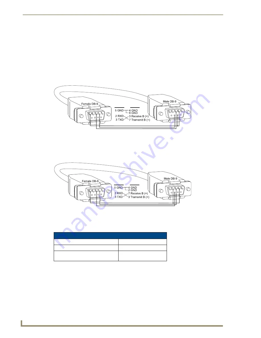
When a controller is attached, use the cable pinout in FIG. 96 and set the toggle switch on the
board to CTL.
When a device is attached, use the cable pinout in FIG. 97 and set the toggle switch on the
board to DEV.
RS-232 Pinout, Toggle Set to CTL
RS-232 Pinout, Toggle Set to DEV
Note:
RS-232 cable length and data rates are limited by the connected RS-232 equipment.
FIG. 96
RS-232 when toggle switch is set to CTL
FIG. 97
RS-232 when toggle switch is set to DEV
RS-232 Voltage Compatibility
TX Recommended (max.) Voltage
+12 V, -8 V
TX Absolute (max.) Voltage
+15 V, -10 V
RX Recommended (min.) Input Voltage
HIGH
≥
2.5 V
LOW <1.0 V
RS-232
RS-422
RS-232
RS-422
Summary of Contents for AutoPatch Modula
Page 6: ...Contents iv Modula Instruction Manual...
Page 12: ...Notices 6 Modula Instruction Manual...
Page 26: ...Enclosure Configurations 20 Modula Instruction Manual...
Page 50: ...Installation and Setup 44 Modula Instruction Manual...
Page 60: ...Wideband Boards 54 Modula Instruction Manual...
Page 64: ...HV Sync Video Boards 58 Modula Instruction Manual...
Page 70: ...S Video Boards 64 Modula Instruction Manual...
Page 74: ...RGBHV HD 15 Boards 68 Modula Instruction Manual...
Page 118: ...Mono Audio Boards 112 Modula Instruction Manual...
Page 124: ...Microphone Input and Phantom Power Boards 118 Modula Instruction Manual...
Page 128: ...SD SDI and HD SDI Digital Video Boards 122 Modula Instruction Manual...
Page 142: ...Cat5 Video and Audio Boards with TXs RXs 136 Modula Instruction Manual...
Page 176: ...Appendix C Paralleling Inputs 170 Modula Instruction Manual...
Page 182: ...Appendix D Adding or Replacing Boards 176 Modula Instruction Manual...


