AMF REECE S-311 Parts And Service Manual Download Page 117

S-311+I

1-7 I

A - INTRODUCTION

Released: 01/2014

E-mail: [email protected]; webside: amfreece.com

Phone: +420 582 309 146; Fax: +420 582 360 606
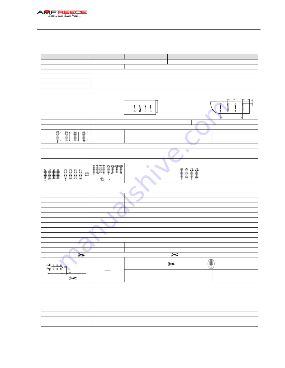
3. SPECIFICATIONS

* Note:


If a customer uses thread size 100 and less, the manufacturer recommends to use the left looper 17.0069.4.019

If you use poor quality threads on the machine, the thread can burn at the needle (producer recommend decrease machine´s speed).

Machine models

AF ST JT

10 - 50 mm

3,0 - 20,0 mm

4 - 8 mm

4 to 20 

4 to 20 

12 mm

in 8,0 mm

Cut before  (CB), cut after (CA), no cut (OFF)

- 0,50 to + 1,2 mm

See section D 3.3 - manual S-311

4-6 mm

0,5-1,5 mm

No Eye; 2,2 x 3,0 mm; 2,8 x 4,2 mm; 3,0 x 4,6 mm; 3,2 x 5,0 mm; 3,4 x 4,2 mm

2,1 mm (

± 0,3 mm electronic adjustment); 2,7 mm (± 0,3 mm electronic adjustment) 

± 1,5 mm 

64 mm 

02.0558.0.111 (Nm 100)

02.0558.1.112 (Nm 110)

80, 100, 120, gimp size 10-30 standard **.

80, 100, 120, gimp size 30-100

L = 16 to 20 mm

L+L  = 23 to 27 mm

1

0,55 MPa = 80 PSI

530 mm (height) x 370 mm (width) x 560 mm (depth)

730 mm (height) x 1100 mm (width) x 700 mm (depth)     + 150 mm distance

64 kg

180 kg

1NPE~60Hz 230 V/TN/S; 1NPE~50Hz 230 V/TN/S

Min. 10A Characteristic C (EN60947-2)

L =86,9db; L =74,8 db; Noise measurement according to EN ISO 3746:1995 

wA

pfA

According to IEC 364-3, IEC 364-5-51 temperature from +5°C do 40°C, relative air humidity from 30 to 80%

16 - 20  mm

1000 - 2000 stitches/min (500 - 1000 rev/min of the drive shaft)

Jacket Sleeve

Single chainstitch

Jeans Fly Front

1 - 6 buttonhole

8 - 160 mm

31 mm

9 - 19 mm

160 mm

Yes

No

Double chainstitch with or without gimp

Jeans Fly Front

0,5 to 2,0 mm (increments of  0,1 mm)

Sewing Speed

Application
Stitch Type
Number of Buttonholes
Distance between Buttonholes

Distance from Fabric Edge 

(horizontal)

Distance from Fabric Edge 

(vertical)

Max. Horizontal Feed Amount

Thread Nipper

Stitch Density

Buttonholes style

Eye type

Fly Bar Length
Length of Crossbar

Number of Stitches in the eye

Number of Stitches in the round end

Clamp Foot Height
Sewing Thickness
Buttonhole Cutting
Cutting Space
Cut position (Y axis)
Bedplate movement
Needle system
Recommended threads*
Upper thread trimming

Lower thread and gimp trimming

Cutting space

Operating Condition
Air pressure
Machine db Level
Machine Head Dimension
Machine Head Weight
Table Dimensions
Machine Weight
Electrical requirements
Line Circuit Breaker

Stitch Bite

CT 16 - 20 mm DT JT

CT 16 - 20 mm DT JS

L

= 3 to 7 mm

(short ends)

max   3,5 mm

0,5 - 1,5 mm

Crossbar density

Jacket Sleeve

A

B

C

D

A

B

C

D

S-311+I

Buttonhole
Length

CT 20 - 24 mm DT JS

20 - 24  mm

2,1 mm (

± 0,3 mm electronic adjustment); 2,7 mm (± 0,3 mm electronic adjustment) 

Stitch Bite (Crossbar)

L = 20 to 24 mm

L+L  = 

mm

1

27 - 31 

Summary of Contents for REECE S-311

Page 1: ...TTONHOLE MACHINE PARTS AND SERVICE MANUAL MACHINE SERIAL No PART NUMBER 97 1930 0 002 This manual is valid from the machine serial No N 190801 version ACL No N 190791 MODEL S 311 AMF is trademark of A...

Page 2: ......

Page 3: ...TTONHOLE MACHINE PARTS AND SERVICE MANUAL MACHINE SERIAL No PART NUMBER 97 1930 0 002 This manual is valid from the machine serial No N 190801 version ACL No N 190791 MODEL S 311 AMF is trademark of A...

Page 4: ......

Page 5: ...ANUAL 97 1930 0 002 ELECTRONIC EYELET BUTTONHOLE MACHINE PARTS AND SERVICE MANUAL 97 1930 0 002 ELECTRONIC EYELET BUTTONHOLE MACHINE PARTS AND SERVICE MANUAL 97 1930 0 002 ELECTRONIC EYELET BUTTONHOLE...

Page 6: ......

Page 7: ...caused by the use of non Genuine AMF Reece parts 6 Shipping or delivery charges There is no service labor warranty for machines sold as uninstalled Equipment installed without the assistance of a cert...

Page 8: ......

Page 9: ...on Customer s Name Customer s Mailing Address Customer s Telephone Number Supervising Mechanic s or Technician s Name Signature of Supervising Technician AMF Reece Technician s Name AMF Reece Technici...

Page 10: ......

Page 11: ...wer and air connection 1 18 6 Thread stand installation 1 19 7 Lubrication 1 20 C PROPER APPLICATION 1 Powerup homeposition 1 21 2 Needle installation 1 22 3 Threading 1 23 D MACHINE CONTROLS 1 Operat...

Page 12: ...rimming mechanism AF LTT 1 55 15 Adjustmentoftheupperthreadpick upheight 1 56 16 Upper trimming and lower interception CT 1 57 17 Mechanismus adjusting for CT gimp 1 60 18 Practical recommendation for...

Page 13: ...e most important safety equipment of all Be sure you understand the proper operation of the machine Never remove safety mechanisms or labels We have made every effort to provide the safest possible ma...

Page 14: ...582 360 606 A INTRODUCTION 2 SAFETY LABELS AND DEVICE 1 Warning 2 Danger possible injury 3 Covers removed possible injury 4 Switch 5 Grounding 6 Rotational direction 7 Standard label 8 Needle bar cov...

Page 15: ...A INTRODUCTION Released 01 2014 E mail service amfreece cz webside amfreece com Phone 420 582 309 146 Fax 420 582 360 606 3 GENERAL MACHINE PARTS DESCRIPTIONS 16 Display 17 Table 18 Control box 19 Han...

Page 16: ...rd 80 100 120 gimp size 30 100 L 14 to 24mm L L 21 to 31mm 1 0 55 MPa 80 PSI 530 mm height x 370 mm width x 560 mm depth 730 mm height x 1100 mm width x 700 mm depth 150 mm distance 64 kg 175 kg 1NPE...

Page 17: ...Mode Cutting Space Cut position Y axis Bedplate movement Needle system Recommended threads Upper thread trimming Lower thread and gimp trimming Cutting space Operating Condition Air pressure Machine d...

Page 18: ...ax 420 582 360 606 A INTRODUCTION 5 BUTTONHOLE DESCRIPTION 1 The first row of stitches 2 The second row of stitches 3 Eye 4 Cutting space 5 Stitch density 6 Bite size 7 The length of a bar 8 The lengt...

Page 19: ...the machine to the power supply when any cover is removed It is forbidden to disconnect all connectors when the machine is switched on and connected to the power supply The electrical components and m...

Page 20: ...th the power supply turn off the main power switch Do not remove paint over damage or in any way change safety labels If a safety label cannot be easily read replace it Long hair and loose clothing ma...

Page 21: ...the beginning of sewn buttonhole especially when sewing the fly bar It is supplied as standard to the following versions LTT AF I and CT I Indexer for sewing the jackets 7 4 Voltage control relay HRN...

Page 22: ...ents of the container with order In the event of an error immediately inform the manufacturer late notification of an error in shipment may result in loss of claim 2 TABLE ADJUSTMENT 2 1 After you wil...

Page 23: ...870 mm S 311 1 11 Released 01 2014 E mail service amfreece cz webside amfreece com Phone 420 582 309 146 Fax 420 582 360 606 B MACHINE ASSEMBLY...

Page 24: ...ains the control system regulator 2 and valve terminal 3 for controlling the pneumatic cylinders 3 2 The machine is connected from the plant If disassembled connect the machine as follows blue pneumat...

Page 25: ...m Phone 420 582 309 146 Fax 420 582 360 606 B MACHINE ASSEMBLY 1 clamp feet up down 3 upper thread draw off 4 upper thread trimming 6 cutting 8 suction Tubes identification air distribution 0 1 2 X di...

Page 26: ...420 582 309 146 Fax 420 582 360 606 B MACHINE ASSEMBLY S 311 AF PNEUMATIC SYSTEM CONNECTION Tubes identification air distribution 0 1 2 X distribution from a regulator 0 1 2 X pneumatic cylinder ident...

Page 27: ...146 Fax 420 582 360 606 B MACHINE ASSEMBLY S 311 CT PNEUMATIC SYSTEM CONNECTION Tubes identification air distribution 0 1 2 X distribution from a regulator 0 1 2 X pneumatic cylinder identification t...

Page 28: ...9 146 Fax 420 582 360 606 B MACHINE ASSEMBLY Tubes identification air distribution 0 1 2 X distribution from a regulator 0 1 2 X pneumatic cylinder identification A B C 1 clamp feet up down 2 clamp fe...

Page 29: ...2 To remove the cover 4 loosen the screw 7 It allows insertion of the panel 8 with the Emergency Stop button inside the cover 4 3 After loosening the screws 10 of the tension pulley 11 tighten the bel...

Page 30: ...tting cylinders is set to 0 4 MPa 4bar from manufacturer by screw 3 and loosening the nut 5 If a material is incorrectly cut check the cutting steel and a pressure on the regulator 4 Note Set lower ai...

Page 31: ...stand together according to the drawing 6 2 Position of the locking ring 1 allows assembly of the thread stand for various thickness of the table top Threaded end of the post 6 must not extend more th...

Page 32: ...9 146 Fax 420 582 360 606 B MACHINE ASSEMBLY 7 LUBRICATION 7 1 There is the fank for oil eycess on the machine 1 7 2 For oil tigthness and removal is important that upper edge of the funnel 2 inserted...

Page 33: ...kwise to the I position 1 2 The display is activated and illuminated The screen 6 displays information about manufacturer and version of program installed in the machine Wait until the main screen 3 a...

Page 34: ...rd D 2 mm Needles 02 0558 1 112 are externally treated and needle shape is adapted for sewing thick material Thicker needles is not possible to use for standard stitching plates 2 1 Lift the transpare...

Page 35: ...09 146 Fax 420 582 360 606 C PROPER APPLICATION 3 THREADING When threading see the pictures below For easy threading use threading devic 1 from accessories kit It is possible to order the threading de...

Page 36: ...1 24 C PROPER APPLICATION Released 01 2014 E mail service amfreece cz webside amfreece com Phone 420 582 309 146 Fax 420 582 360 606 3 2 Lower thread tilt back the rear cover 1 and lift the machine h...

Page 37: ...imp The appearance and quality of the buttonhole may be affected by one or more of the following stitch density number of stitches in the first and the second row of stitches number of stitches in the...

Page 38: ...sewn fabric is cut and the upper thread is trimmed clamp feet rise and machine returns to its home position 1 5 When the clamp feet are up it is possible to move the fabric for sewing the next buttonh...

Page 39: ...FO N E L C OR G I G D C S I I V I S E C N NE R CT ON S E U I R ES P L OW PP S 311 1 27 Released 01 2014 E mail service amfreece cz webside amfreece com Phone 420 582 309 146 Fax 420 582 360 606 D MAC...

Page 40: ...ne controls in the manual 2 DISPLAY INFORMATION Display messages standard Ready Busy error error messages start with letter E see Troubleshooting section Buttonhole counter Button for easy threading B...

Page 41: ...ay Round eyelet AF RDE Number of stitches in the eye range 4 20 stitches Eye start correction Y axis range 2 0 Eye start correction X axis range 1 0 Bedplate feeding in the eye range 0 100 Buttonhole...

Page 42: ...ding in first and second row of stitches range 0 100 Return to main display Caution If E 50 appears on the display total buttonhole lenght is exceeded Example The S311 CT machine is supplied to sew th...

Page 43: ...he second row of stitches in sewing fly bar range 5 stitches Number of removed or added stitches at the end of the second row of stitches before sewing fly bar range 5 stitches The size of the side sh...

Page 44: ...re 1 stitch Number of stitches which are sewn with double density locking stitches at buttonhole start range 0 5 stitches Number of stitches which are sewn by slow speed at buttonhole start range 0 9...

Page 45: ...606 D MACHINE CONTROLS 7 SEWING SPEED SETTING FOR THE ROUND EYE AF RDE Number of stitches which are sewn By slow speed at buttonhole start range 0 9 stitches speed 1000 spm Sewing speed range 1000 20...

Page 46: ...ece cz webside amfreece com Phone 420 582 309 146 Fax 420 582 360 606 8 BUTTONHOLE COUNTERS Button for counting upward Button for counting descending RESET button SET The counter range adjustment rang...

Page 47: ...ace distance between first and second row of stitches range 0 2 1 2 mm Stitches distance from cut to inner stitches of the eye range 0 2 1 2 mm Buttonhole cut correction in X axis range 1 5 mm Buttonh...

Page 48: ...ce cz webside amfreece com Phone 420 582 309 146 Fax 420 582 360 606 10 ROUND EYE CUTTING SETTING No cutting Cut after sewing Buttonhole cut correction in X axis range 1 5 mm Buttonhole cut correction...

Page 49: ...clamps and automatic sewing start Button for machine type setting Program version Buttonhole copying Button for password 1 2 3 Password Return to previous display I O TEST Return to previous display R...

Page 50: ...gth for all buttonholes in one cycle Imitation no cut buttonholes of different length can be included in the sewing cycle Modification CT to prevent the machine from damage the length of buttonholes i...

Page 51: ...s the button program number setting The numerical display appears on the screen Choose program number 1 and press 2 Press button The screen where it is possible to set the order of sewn buttonholes ap...

Page 52: ...ic to check if the cut is clean Progress Insert the fabric under the clamp feet switch the foot pedal into the first position hold this pedal in this position and press button 1 Cutting lever will cut...

Page 53: ...TANDARD BUTTONHOLE SHAPES SET BY THE MANUFACTURER There are two types of zero buttonhole preset in the program one type with eye and fly bar for AF CT LTT modifications and second type of round eye fo...

Page 54: ...sensor for needle bar position when the machine is stopped BQ1 The sensor for table feeding when sewing 2 1 Rotate the hand wheel 7 until the marking is on the top white point The needle bar has to be...

Page 55: ...te 4 BQ2 8 after loosening the screws 3 to approximately 14 mm Remove the right cover of the bedplate 9 to access to the plate 4 3 2 After removing the left cover of the table 1 adjust the sensor BQ3...

Page 56: ...ck 2 of the needle bar after loosening the screws 3 of the bevel gear so that screw 8 in the needle bar is on the left and tighten the screws When you sew a side stitch the distance between the needle...

Page 57: ...port is decreased if the washer is added in B direction if the washer is removed the support is increased in A direction The washers are supplied with the thickness 0 1 19 0019 6 405 or 0 2 mm 19 0019...

Page 58: ...s 5 from left to right in the X axis 6 2 The adjust feet 2 clamp against the plates 9 for 1 2 2 0mm overlap 6 3 Remove the side table covers 6 by removing the screws 7 6 4 Insert the clamp plates 1 in...

Page 59: ...lockwise decreases spreading counterclockwise increases maximum is 2 5 mm on one clamp plate Check it with stepping section D2 to the place where is the stitching plate between the clamp plates The ed...

Page 60: ...use the same size of the knife eye When using the different eye size the buttonhole will deform or the eye stitches can be damaged The point of departure for the cutting mechanism adjustment is the n...

Page 61: ...ten the screws 8 4 The knife stop in the anvil 6 adjust for 70 mm after loosing the screws 7 8 5 The pressure of the pneumatic system is adjusted with the regulator 8 for 0 6 MPa The pressure for cutt...

Page 62: ...0 582 309 146 Fax 420 582 360 606 E STANDARD MACHINE ADJUSTMENT 8 7 The knife attachment into cutting steel with the screw needs to be done only manualy The tool is used only for loosing too tight set...

Page 63: ...ETTING THE NEEDLE BAR HEIGHT 9 1 Remove the machine head front cover 9 2 Turn the handwheel 1 and adjust the needle bar 2 to the lowest position 9 3 Insert the gauge 5 height 9 5 mm between the needle...

Page 64: ...of the needle 7 By turning the handwheel raise the needle bar from the lowest position to insert a gauge 4 by its higher end between gauge support and the needle bar end 11 3 After loosening the scre...

Page 65: ...so the sewing thread does not go between the right looper and spreader Left 0 01 mm minimum so the sewing thread goes between the right looper and spreader 12 3 Check clearance between needle 7 and s...

Page 66: ...t is such 13 1 To set the bite to 2 1mm 2 3 mm CT loose the nut 3 and move the pin 1 to the left all the way to the end stop towards the edge of the stop 2 13 2 To set the bite to 2 7mm loose the nut...

Page 67: ...the trimming knife 1 so that the left side of the knife was covered with the right side of the throat plate 14 3 Position the tip of the trimming knife 1 0 9 mm in front of the needle 6 by loosening s...

Page 68: ...aterials it is possible to increase this distance 15 5 Loose the screws 10 to adjust the clereance between clamps of the nipper 6 7 and the screw 11 for the distance 3 mm 15 6 Adjust the clereance bet...

Page 69: ...hold the lower thread for next buttonhole sewing When the trimming knife moves the thread holder must move over the throat plate without binding To adjust loosen the nut of the screw 14 and screw out...

Page 70: ...3 8 mm from the top shear to the top of the clamp plate 5 by loosening or tightening screw 11 Tighten the screw 10 and test the cutting of thread If trimming is not correct change the dimension to 3...

Page 71: ...gimp trimming Time for the clamp feet elevation before trimming knives activation range 0 10 i e 0 100 ms initialization 4 Time for the clamp feet elevation during trimming knives activation range 0...

Page 72: ...the thread end is shorter after the throat plate trimming Over tension in stretcher might cause the buttonhole deformation in eye The gimp guide adjustment in base Thanks to adjusting gimp guide in ba...

Page 73: ...EYELET 18 1 Pull out gimp thread from guide with spring gimp thread is gotten out from thread plate 18 2 Parameter for electronic adjustment of trimmed threads tails must be adjusted for 26 mm 18 3 G...

Page 74: ...gimp are separated upward and downward by thread catching plate 1 2 The clamp fixing plate 2 ensures the correct holding of the upper and gimp thread by lower thread clamp 3 and gimp clamp 4 3 Loosen...

Page 75: ...fixing knife 6 to obtain no clearance between them Adjust the upper edge of the fixing knife 6 to be aligned with knife 7 a 4 Align the upper and lower spring 16 17 with fixing knife 6 Spring boss 16...

Page 76: ...gn the fixing knife face 6 with mark on the knife 7 The lower thread clamp 3 is closed in this position and retains lower thread d looper thread hauling LTT d 1 Loosen two screws 19 d 2 Turn the knife...

Page 77: ...asses through are smooth and polished with no burrs or sharp edges When using lower quality thread it is necessary to exchange the spring with the spare one which is in the drawer of the machine 20 1...

Page 78: ...mal 750 Luxes 1 CLEANING AND MAINTENANCE OF THE MACHINE 1 1 Switch the power off and disconnect the air supply 1 2 For cleaning and maintenance remove the clamp feet by removing the protecting latches...

Page 79: ...f the condensate and possible replacement of the filter element 9 The level of condensate must be 10 mm below the filter inside of the desliming receptacle 10 Lower ring of the nut 12 signalizes this...

Page 80: ...operation visual check external and internal mechanism lubrication of needle bar and sewing mechanism fill oil into reservoir with oil level indicator once a month 300 hours of operation check the cl...

Page 81: ...edle and ball bearings which in combination with two lubrication circuits significantly decrease required maintenance Circuit I for lubrication of the arm has oil in reservoir of the barrel The lubric...

Page 82: ...r similar quality 4 2 The amount of oil in the reservior 15 is indicated by the red mark Too much oil may cause its overflowing from the base area 4 3 The reservoir is filled by approximately 10 cm3 o...

Page 83: ...d after opening the rear cover and after turning the race by hand according to the section E2 point 2 3 4 6 Remove the side covers unscrew the screws 16 and loosen the screws 17 Apply several drops of...

Page 84: ...parts from the machine To take these parts out it is necessary to perform the partial dismantling of the machine remove covers dismantle the machine arm and remove the frame 5 2 Aluminium and duralum...

Page 85: ...3 5 1 Upper Thread Trim Cylinder Thread Pick Up Cylinder 4 2 3 5 1 Hold Up Thread Cylinder LTT Extra part other models 0 6 MPa 1 4 1 2 3 0 4 MPa 4 2 3 5 1 Cutting Cylinder 2 1 Bag Suction Clamps Cyli...

Page 86: ...S 311 1 74 Released 01 2014 E mail service amfreece cz webside amfreece com Phone 420 582 309 146 Fax 420 582 360 606 G DOCUMENTATION ELECTRICAL DIAGRAM...

Page 87: ...S 311 ACL Released 01 2014 E mail service amfreece cz webside amfreece com Phone 420 582 309 146 Fax 420 582 360 606 MODEL S 311 ACL OPERATING INSTRUCTIONS...

Page 88: ......

Page 89: ...INSTALLATION FOR SWITCH VALVE OF CUTTING 2 2 LPE CUTTING BLOCK INSTALLATION D OPERATING THE MACHINE FUNCTIONS 1 SEWING A BUTTONHOLLE 2 DESCRIPTION OF THE ACL SCREEN 3 SETTING UP ACL DISPLAY 4 LAPEL SY...

Page 90: ......

Page 91: ...CL e LTT ACL b AF ACL LP1 f LTT ACL LP1 c AF ACL LP2 g LTT ACL LP2 d AF ACL LPE h LTT ACL LPE 1 AF ACL and LTT ACL handles the widest range of sewing 13 38 mm without change of cutting steel 2 AF ACL...

Page 92: ...S 311 ACL 1 6 ACL Released 01 2014 E mail service amfreece cz webside amfreece com Phone 420 582 309 146 Fax 420 582 360 606 A INTRODUCTION 2 TERMINOLOGY OF MACHINE PARTS 1 Sliding block 2 Motor...

Page 93: ...g 175 kg 1NPE 60Hz 230 V TN S 1NPE 50Hz 230 V TN S Min 10A Charakteristik C EN60947 2 L 86 9db L 74 8 db measured according EN ISO 3746 1995 wA pfA According to IEC 364 3 IEC 364 5 51 temperature from...

Page 94: ...ve humidity from 30 to 80 13 38 mm 13 26 mm 13 30 mm 1000 2000 stitches per minute 500 1000 rotation per minute of the drive shaft 0 5 2 0 mm each step 0 1 mm Performance of the machine Stitch density...

Page 95: ...numbers downloaded in the machine show up Wait until the machine show up Wait until the main screen 3 appears 3 If the error message E01 appears in the panel 4 machine not in home position press 5 If...

Page 96: ...eal the reflective foil 2 into the hole already made in the bedplate 3 Put the vertical holder of the sensor 3 through the opening in the cover and fit it onto the machine bedplate 4 4 Mount the senso...

Page 97: ...14 E mail service amfreece cz webside amfreece com Phone 420 582 309 146 Fax 420 582 360 606 C MACHINE INSTALLATION 2 KIT ACL LPE INSTALATION To connect the pneumatic folow the instruction in this sch...

Page 98: ...Connect cable 06 1900 0 015 into marked terminal in electrobox 2 Connect cable 06 1900 0 016 into valve connector 3 Fasten then opposite cable end into the plug on electrobox and lock with screws 2 2...

Page 99: ...the pedal the clamp feet lift up 4 Pressing the pedal down into the second position starts sewing of the buttonhole shape selected in the program Once the buttonhole is sewn the fabric cut and upper t...

Page 100: ...nholes sewn daily Key for easy threading Optional accesory optical sensor Machine home positon Key to set up sewing speed Key to set up cutting Service setting Button to set up buttonhole finishing Mo...

Page 101: ...ax 420 582 360 606 D OPERATING THE MACHINE FUNCTIONS 3 SETTING UP ACL DISPLAY Key to select the machine mode S 311 Main screen Password 1 2 3 Press key to select the code Back to main screen To confir...

Page 102: ...LP1 ACL LP2 and ACL LPE which differ in the range of cut LAPEL SYSTEM Lenght of cut ACL LP1 ACL LP2 ACL LPE Lenght of cut in buttonhole with eye 13 26 mm 13 30 mm 13 30 mm Lenght of cut in lapel butt...

Page 103: ...utomatically according to the selected model in this case 13 26 mm this type of buttonhole is used on jacket front If you want to modify the buttonhole parameters follow instructions in chapters on pa...

Page 104: ...webside amfreece com Phone 420 582 309 146 Fax 420 582 360 606 4 2 SETTING UP THE LAPEL BUTTONHOLE FOR ACL LP1 ACL LP2 ACL LPE VERSION Back to main screen Back to main screen Setting up eye type Sett...

Page 105: ...irst with the keypad Confirm by pressing ENT Then press the second key and select the next buttonhole number in order 1 Repeat this process until all buttonholes to be sewn are set If you select 0 at...

Page 106: ...buttonhole type that is to be sewn and make the work easier for the operator At the same time it reduces errors during work process The optical sensor consists of two parts the sensor itself and refl...

Page 107: ...ENT Then press the second key and select the next hole number in order 2 Cycle mode screen with optical sensor activated 3 Press to save the buttonholes set up in the program 1 Go back to main screen...

Page 108: ...s enables changing the cut within a given range when the buttonhole length is changed 1 Adjust the screening 2 so that its edge stays in the alignment with sliding block edge 1 2 Distance between the...

Page 109: ...version ACL LP1 LP2 LPE see section C 4 1 2 Adjust the requested cutting lenght on the display 3 Insert the paper between knife and block and test the cut with button for cutting 4 If the adjusted pa...

Page 110: ...N THE REGULATORS OF THE FILTER UNIT Correct pressure adjustment affect the cutting knifes life cycle 1 Adjust pressure 0 6 MPa 0 5 MPa on the main regulator 2 Adujst pressure 0 4 MPa on cutting regula...

Page 111: ...S 311 I Released 01 2014 E mail service amfreece cz webside amfreece com Phone 420 582 309 146 Fax 420 582 360 606 MODEL S 311 I OPERATING INSTRUCTIONS...

Page 112: ......

Page 113: ...SEWING 2 THREADING D MACHINE FUNCTIONS CONTROLS 1 SEWING A BUTTONHOLE 2 SETTING UP THE INDEXER DISPLAY 3 INDEXER SCREEN DESCRIPTION 4 BUTTONHOLE TYPE SETTING 5 CHANGE OF BUTTONHOLE PARAMETERS SETTING...

Page 114: ......

Page 115: ...buttonhole types see S311 section A chapter 4 Specifications with or without cut during one sewing cycle There is a thread nipper attached to the device which facilitates better quality of finished b...

Page 116: ...2014 E mail service amfreece cz webside amfreece com Phone 420 582 309 146 Fax 420 582 360 606 A INTRODUCTION 2 SAFETY LABELS AND EQUIPMENT Indexer For detailed description see S 311 section A chapte...

Page 117: ...4 3 IEC 364 5 51 temperature from 5 C do 40 C relative air humidity from 30 to 80 16 20 mm 1000 2000 stitches min 500 1000 rev min of the drive shaft Jacket Sleeve Single chainstitch Jeans Fly Front 1...

Page 118: ...Phone 420 582 309 146 Fax 420 582 360 606 B MACHINE ASSEMBLY S 311 I AF PNEUMATIC SYSTEM CONNECTION 1 clamp feet up down 2 clamp feet spreading 3 upper thread draw off 4 upper thread trimming 5 9 thr...

Page 119: ...582 309 146 Fax 420 582 360 606 B MACHINE ASSEMBLY S 311 I CT PNEUMATIC SYSTEM CONNECTION 1 clamp feet up down 2 clamp feet spreading 3 upper thread draw off 4 upper thread trimming 5 9 thread nipper...

Page 120: ...r and numbers of programs uploaded in the machine appears Wait until the main screen 3 appears on the display 1 3 If E01 error message is shown in the box 4 on the display the machine is not in the ho...

Page 121: ...ER APPLICATION 2 THREADING Threads are threaded as shown in the pictures below For easy threading use threading devic 1 from the machine accessory Threading device 2 can be ordered separately order nu...

Page 122: ...12 I C PROPER APPLICATION Released 01 2014 E mail service amfreece cz webside amfreece com Phone 420 582 309 146 Fax 420 582 360 606 2 2 Lower thread threading can be done after tilting the back cove...

Page 123: ...covers 1 b Disconnect air pipes from cylinders c Loose screws 2 of the right side feet holder and take it out d Hold the device 3 and pull it to the left to take it out e Remove the clamp plates 4 an...

Page 124: ...threading The appearance and quality of the buttonhole may be affected by one or more of the following stitch density number of stitches in the first and the second row of stitches number of stitches...

Page 125: ...and the work piece will be clamped Releasing the foot pedal will lift the clamps up again 1 4 Pressing the foot pedal down into the second position will start sewing the buttonhole which has been sele...

Page 126: ...309 146 Fax 420 582 360 606 2 SETTING UP THE INDEXER DISPLAY Button for machine version selection S 311 Main display Password 1 2 3 Button for setting up the code Back to main display Back to previous...

Page 127: ...e options Home position Hand presetting position of Indexer only at setting automatic mode Number of cycle mode 1 50 Function cycle mode 0 Disfunction cycle mode at setting 0 machine sews only one but...

Page 128: ...NHOLE TYPE SETTING Cycle mode button Button for setting number for cycle mode Back to main display Number of programmed buttonhole option Confirm by pressing button We can set type of other buttonhole...

Page 129: ...section D Back on main display After parameters change press button to switch back to main display Confirm by pressing button We can set distance for other buttoholes in cycle mode with the same proce...

Page 130: ...360 606 7 INDEXER ERROR REPORTS Back to main display After parameters change press button to switch to main display Indexer main display For detailed trouble description and its removing see the trou...

Page 131: ...oose clamp holders screws 1 on the left and right side of the Indexer 1 2 Set up a gap of 0 5 0 7 mm between feet and desktop feeler gauge can be used 1 3 Verify the setting by pressing the button The...

Page 132: ...sary to hold the minimal play 2 1 Check whether the play on the machine is set onto 2mm in both positions of the Indexer Use this display buttons to make a move 2 2 If the 2 mm distance is not adjuste...

Page 133: ...nce of 25 mm between them The total length is 75 mm the first buttonhole is always sewn in indexer home position X number of buttonholes 1 fixed in place x distance between them 2 mm minimal play betw...

Page 134: ......

Page 135: ...ce amfreece cz webside www amfreece com Phone 420 582 309 146 Fax 420 582 360 606 TROUBLESHOOTING TABLE OF CONTENTS 1 Introduction 2 2 2 Faults without error messages 2 3 3 The electronic system error...

Page 136: ...approval of the manufacturer may cancel the warranty To obtain the highest quality buttonhole maintain the following values clearance between the needle and the loopers is 0 05 to 0 1 mm 0 002 to0 00...

Page 137: ...the sewing mechanism Set the distance to 0 05 mm E10 E11 page 1 51 page 1 52 Defective spreader return springs Replace the springs Sewn fabric is incorrectly cut Knife and cutting steel are incorrectl...

Page 138: ...ed to equipped the machine with the thread nipper for the following 03 5519 3 013 Indexer clamp plates do not close Air supply is not connected Check air supply Clamp plates do not hold the material p...

Page 139: ...to reset this error message Cutting lever error during cutting Check BQ7 sensor and air supply E 06 Cutting lever is not home Check BQ7 sensor and air supply E 07 Low voltage Check power supply voltag...

Page 140: ...ters according to sewing range of machine type E 56 ACL LP lapel cutting lenght parameter error Check the lapel cutting length according to moveable support plate range of machine type E 57 ACL LP lap...

Page 141: ...Emergency stop button Change the stop button PN 12 0008 4 563 Disconnected girth Em stop Check the girth button Indexer motor does not hold its position Motor driver defect Change 12 0008 4 754 Disco...

Page 142: ......

Reviews: