Excalibur PCI Pentium ISA Motherboard User's Guide
39
Step 4 Connect the Power Supply
The power supply should match the physical configuration of the chassis. Make sure that the power switch is Off
before assembly.
Before attaching all components, make sure that the proper voltage has been selected. Power supplies often can run on
a wide range of voltages and must be set (usually via a switch) to the proper range. Use at least a 230 watt power
supply that has built-in filters to suppress EMI radiated emissions.
Connect to P5 and P2
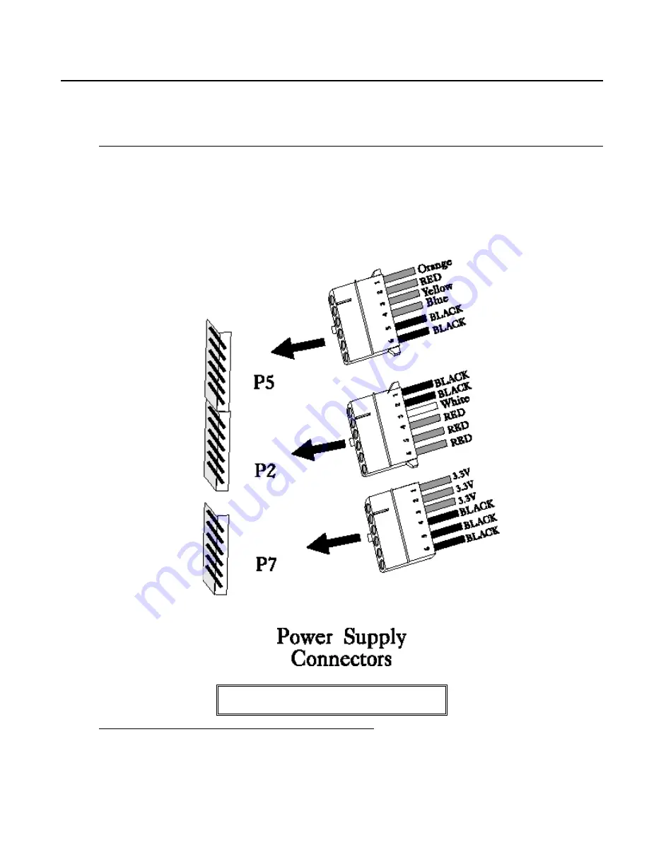
Attach the power supply cables to P5 and P2 on the motherboard. AT-compatible power supplies have two 6-pin
connectors. The 6-pin connector with 3 red wires and 2 black wires is connected to P5 and the remaining 6-pin
connector is connected to P2, as shown below. P7 is an auxiliary power supply connector.
Caution
P7 is not a 5V power connector.
Summary of Contents for Excalibur PCI
Page 5: ...Excalibur PCI Pentium ISA Motherboard User s Guide 5 ...
Page 7: ...Excalibur PCI Pentium ISA Motherboard User s Guide 7 ...
Page 17: ...Excalibur PCI Pentium ISA Motherboard User s Guide 17 ...
Page 19: ...Excalibur PCI Pentium ISA Motherboard User s Guide 19 ...
Page 27: ...Excalibur PCI Pentium ISA Motherboard User s Guide 35 ...
Page 52: ...Chapter 5 AMIBIOS POST 48 ...
Page 60: ...Chapter 5 AMIBIOS POST 56 ...
Page 64: ...Chapter 6 WinBIOS Setup 60 ...
Page 82: ...Chapter 6 WinBIOS Setup 78 ...
Page 86: ...Chapter 6 WinBIOS Setup 82 ...
Page 88: ...Chapter 6 WinBIOS Setup 84 ...


