Amcrest AMDV108116 User Manual Download Page 91


91 


4.10.4.1 Schedule  

  
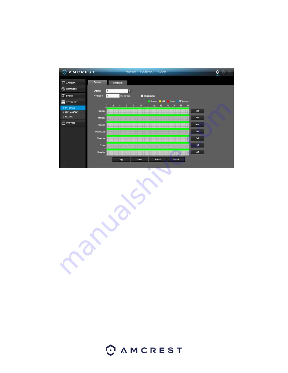
This screen is used to specify the recording schedule for both recorded video and snapshots.  


Below is an explanation of the fields on the Record settings screen:  

• 

Channel:

 This dropdown box allows the user to pick which channel they would like to change video recording 

settings for.  

• 

PreRecord:

 This field allows the user to capture extra video that occurs before an event. Up to 30 seconds of 

video prior to a recording event can be captured to provide context to a recording.  

• 

Redundancy:

 This checkbox allows the user to enable the redundancy backup feature. This feature allows the 

DVR to record video to two hard drives concurrently to ensure that in the case of a hard drive failure, the 
recorded data may be backed up to another hard drive.   

o


Note: This function only works if the HDD has two hard drives installed.  

o


Note: One hard drive must be designated as redundant from the HDD Manager menu. See section  
4.10.5.2 for more details.  

• 

Record Types: There are 4 types of recordings:  

o


Regular:

 Regular recording means that the DVR captures all footage for the specified time period. 

Regular recording is represented by green.  

o


MD:

 Motion Detection recording means that the DVR captures only footage when the motion 

detection alarm is activated. MD recording is represented by yellow.  

o


Alarm:

 Alarm recording means that the DVR captures only footage when an alarm is activated. 

Alarm recording is represented by the color red.  

o


MD & Alarm

: This type of recording is a combination of motion detection and alarm footage, and 

records when either a motion detection alarm or general alarm is activated. MD & Alarm recording 
is represented by the color white.  

To set a recording schedule for your device, click on the 

set

 option located on the right of the day you wish to 

set the schedule. The system allows for the configuration of up to 6 different time periods. 

Summary of Contents for AMDV108116

Page 1: ...Amcrest AMDV4M4 4MP UltraHD 4CH HDCVI DVR User Manual...

Page 2: ...nnection and Installation 14 3 1 Check Hardware 14 3 2 Hard Drive Installation 14 3 3 Connection Port Information 15 3 4 DVR Assembly Guide 20 4 Overview of Navigation and Controls 24 4 1 Startup and...

Page 3: ...Qs Troubleshooting 129 Appendix A Compatible Backup Device List 133 Appendix B Compatible CD DVD Device List 139 Appendix C Compatible Display List 139 Appendix D Compatible Switch List 140 Appendix E...

Page 4: ...d prevent unauthorized access please make sure to follow the steps below Always make sure that your camera has the latest firmware as listed on www amcrest com firmware Never use the default password...

Page 5: ...nsported stored and used only in the specified environments as stated above 6 Accessories Be sure to use only the accessories recommended by manufacturer Before installation please open the package an...

Page 6: ...ses such as a flash drive portable HDD or even a CD DVD burner Advanced Playback Function This device supports independent real time recording for each channel and can support search fast forwarded pl...

Page 7: ...iety of network hardware Note There may be slight differences in functionality due to the existence of different product series 2 Overview and Controls This section provides information about the phys...

Page 8: ...he cable A You can connect to the control devices such as speed dome PTZ RS485_B It is the cable B You can connect to the control devices such as speed dome PTZ B 2 Power Input port Input 12V DC 3 Net...

Page 9: ...ssed high definition video and multiple channel data to the HDMI port of the display device 9 USB 2 0 port Connect to USB storage device mouse burning DVD ROM etc 10 GND Ground end 2 3 Device Connecti...

Page 10: ...t to input device number so that you can control it 3 Forward Various forward speeds and normal speed playback 4 Slow play Multiple slow play speeds or normal playback 5 Next record In playback mode p...

Page 11: ...ch current activated control go left or right In playback mode click up down button to switch playback channel In 1 window playback mode click left right button to control playback speed Aux function...

Page 12: ...up drop down list In the input box you can select input methods Left click the corresponding button on the panel and you can input numeral English character small capitalized Here stands for backspac...

Page 13: ...setting applies for current selected channel If you are in multiple window mode system automatically switches to the corresponding channel Exit current menu without saving the modification Press midd...

Page 14: ...for your DVR are present and accounted for To check what is included with your purchase go to http amcrest com hdcvi security camera systems html and find the product you purchased then scroll down a...

Page 15: ...first and then slide the cover off 3 3 Connection Port Information 3 3 1 Power Supply Connection Please check to make sure the input voltage is correct and the power button is in the off position when...

Page 16: ...int lap welding and oxidation 3 3 2 2 Video Output Connection Information Video output includes a BNC PAL NTSC1 0VP P 75 output a VGA output and a HDMI output The system supports BNC VGA and HDMI outp...

Page 17: ...ormal Close e When you are connecting two DVRs or one DVR and one other device please use a relay to separate them 3 3 4 2 Alarm Output Connection Information The alarm output port should not be conne...

Page 18: ...ng alarm inputs Normal Open or Normal Close type Please parallel connect COM end and GND end of the alarm detector Provide external power to the alarm detector Please parallel connect the Ground of th...

Page 19: ...polarity 1000VAC 1 minute Between contacts and winding 1000VAC 1 minute Surge voltage Between contacts with same polarity 1500V 10 160us Length of open time 3ms maximum Length of close time 3ms maxim...

Page 20: ...ted by this USB port please see Appendix F 3 4 DVR Assembly Guide Before setting up the HDCVI DVR you will probably need the following items These items are not included A computer monitor or TV with...

Page 21: ...21 2 Connect a USB mouse to the front of the DVR 3 Connect an Ethernet cable to your router and then connect the other end of the cable to the DVR...

Page 22: ...camera s video cable and connect the camera power extension cable to the camera s power cable There should be a tag on the video cable to help you make sure the right end of the cable is at hand 5 Con...

Page 23: ...23 6 Connect the camera power extension cable to one of the camera power cables connect this power cable into the power brick and then plug the cable into an electrical socket...

Page 24: ...power on off button Always use a stable current If necessary an Uninterruptable Power Supply UPS is a good way to ensure power stability Please follow the steps listed below to boot up the device Plug...

Page 25: ...resume previous working status after power failure 4 2 Startup Wizard After turning the system on the default video display shows multiple windows To bring up the login screen left click the mouse or...

Page 26: ...mbers Toll Free 888 212 7538 International Callers Outside of US 1 713 893 8956 USA 713 893 8956 Canada 437 888 0177 UK 203 769 2757 o Email Amcrest Customer Support support amcrest com The next scree...

Page 27: ...k the Next Step button at the bottom of the screen The next screen that comes up is the Schedule settings screen Make sure to click the tabs at the top for Record and Snapshot to configure those setti...

Page 28: ...ess is the Network settings screen Once you are satisfied with the settings on this screen click the Finished button at the bottom of the screen Once more note that these settings can be changed at an...

Page 29: ...nd then drag it to the channel 2 window then release the left mouse button This will switch channel 1 with channel 2 s position Use the middle mouse button to control how the windows are split You can...

Page 30: ...a zone You can see the interface shown below Push the middle mouse button at the center of the zone you want to zoom into and move the mouse You can see the interface as shown below Right click the m...

Page 31: ...hots 4 4 Right Click Menu By right clicking the mouse on the screen the following menu opens up 4 4 1 Video Viewing Options The DVR supports many different video viewing options of the live streamed c...

Page 32: ...e rotation of the camera in 8 different directions If the buttons on the front panel of the DVR are used then only four of the directions will be accessible up down left right In the middle of the eig...

Page 33: ...o to menu Note The name of the command will be grayed out if the function is not supported See below for detailed information on each PTZ function To configure the functions above click the Settings b...

Page 34: ...tion allows for the use of multiple presets stringed together To create and manage tours follow the steps below Ensure you have more than 1 preset configured already Input the tour value and the prese...

Page 35: ...raining the area of movement for the cameras during any PTZ function To set up borders move the camera using the PTZ controls to the left limit then click Left to designate that position as the left l...

Page 36: ...uration settings 4 4 2 8 Aux On Off The camera may have an auxiliary function and this feature enables its use The aux number corresponds to the device s slot on the PTZ decoder 4 4 3 Color Settings U...

Page 37: ...e number the higher the contrast is You can use this function when the whole video brightness is OK but the contrast is not correct Please note the video may become hazy if the value is too low If thi...

Page 38: ...n to go to the main menu interface 4 5 2 Video Viewing Options These buttons allow the user to select a viewing mode for live viewing 4 5 3 Favorites Click the button and the system displays the favor...

Page 39: ...he HDD manager interface It is used to view and manage HDD information Please refer to chapter 4 10 5 2 for more information 4 5 9 Network Click the button and the system goes to the network interface...

Page 40: ...t it and pop up the following dialogue box It allows you to conveniently backup files logs configurations or update the system See the image below for the USB Device Popup screen Please refer to chapt...

Page 41: ...ion Info Network View information about the network or test the network status Info Event Display information about events that triggered recording Info Log Display system logs of critical events Sett...

Page 42: ...to search the picture or the recorded file You can select to play from the read write HDD from a peripheral device or from a redundancy HDD Before you select to play from the peripheral device please...

Page 43: ...8 1 3 for detailed information on how to mark video for playback 7 Advanced Search Click this button and you can view the picture recorded file list of the current day The file list is used to displa...

Page 44: ...Click the Start button the snapshot picture will be saved to the specified path Mark button Allows for the marking of a file for later ease of access You can refer to chapter 4 8 1 3 for detailed info...

Page 45: ...previous position Click the Backup button after clip to save current content in a new file You can clip one channel or multiple channels The multiple channel clip operation is similar to the one chan...

Page 46: ...el This feature is useful as it allows users to search a channel s recorded files for motion without having to change the recording type to a motion detection recording During the multiple channel pla...

Page 47: ...lements accurate playback for the first time Play is clicked System does not support precise playback for screenshots System supports synchronized playback and non synchronized playback The synchroniz...

Page 48: ...ion in the current channel by time Modify Double click one marked information item The system pops up a dialogue box that allows for editing of the marked information The marked information s name can...

Page 49: ...DVD burners USB devices and eSATA devices To backup recorded files select the backup device the channel file start time the end time then click the add button so the system can begin a search for the...

Page 50: ...ialogue box appears informing the user about a successful backup Note There are two file format options DAV ASF The file name format is usually Channel number Record type Time In the file name the YDM...

Page 51: ...tions The Shut down option turns off the DVR The Logout option logs off the current user and shows the login screen so another user may login The Reboot option reboots the DVR Note If the proper autho...

Page 52: ...ive is damaged and should be replaced Type This field shows the read write properties of the connected hard drive Total space This field shows the total capacity of the connected hard drive Free space...

Page 53: ...53 4 9 1 2 Record Info This screen is used to view information on recorded video specifically recording start time and end time for all media based on each hard drive...

Page 54: ...s well as resolution used for each camera All data is measured in Kilobytes per Second KB s 4 9 1 4 Version This screen shows version information for the DVR Here information such as device model chan...

Page 55: ...to display network information It consists of 3 screens Online Users Load and Test 4 9 3 1 Online Users This screen is used to monitor and manage users who are online With the proper system access le...

Page 56: ...atus is shown as offline if the DVR is disconnected from the internet The bottom panel is a graph that shows the fluctuation in the send and receive speed 4 9 3 3 Network Test This screen is used to t...

Page 57: ...an click the button on the right panel to begin the Sniffer Click the grey stop button to stop Please note the system cannot sniff several network adapters at the same time After the Sniffer begins yo...

Page 58: ...are set click Search to show log items that match the criteria Clicking on a line item then clicking the Details button or double clicking the line item shows the detail screen The backup button allow...

Page 59: ...ccordingly You can use this function when the whole video is too dark or too bright Please note the video may become hazy if the value is too high The recommended value ranges from 40 to 60 Contrast T...

Page 60: ...n list Frame Rate This dropdown box allows the user to select a frame rate Frame rate settings range from 1f s to 25f s in NTSC mode and 1f s to 30f s in PAL mode Bit Rate Type This dropdown box allow...

Page 61: ...box allows the user to select image quality Quality is adjusted on a scale of 110 Snapshot Frequency This dropdown allows the user to select the snapshot interval The value ranges from 1 to 7 seconds...

Page 62: ...privacy mask zone cannot be viewed by user when system is in preview status o Monitor means the privacy mask zone cannot be viewed by the user when system is in monitor status Time Display This button...

Page 63: ...is used to modify the channel names Each field supports a maximum of 31 characters To revert to default settings click the Default button near the bottom left hand corner To confirm settings click th...

Page 64: ...the fields on the TCP IP settings screen IP Version This dropdown allows the user to select the IP version The two options are IPV4 and IPV6 MAC address This field shows the DVR s MAC address which is...

Page 65: ...than the MTU of the gateway This way packets can be reduced and the network transmission efficiency be enhanced The following MTU values are for reference only o 1500 Ethernet information packet maxi...

Page 66: ...f any changes are made to the settings on this screen Also ensure that port values do not conflict Below is a screenshot of the connection screen Below is an explanation of the fields on the Connectio...

Page 67: ...stands for Dynamic Domain Name Server This technology is used to automatically update name servers in real time to help the DVR maintain a persistent address despite changes in location or configurati...

Page 68: ...is field allows the user to enter the domain name from the Quick DDNS service Email Address This field allows the user to enter the email address associated with the Quick DDNS account To revert to de...

Page 69: ...o Newly added IP addresses are enabled by default but can be disabled or added to the block list If the system is in trusted sites mode select the IP address and delete it to remove it from the list I...

Page 70: ...eld allows the user to enter the port that corresponds to the selected SMTP server User Name This field allows the user to enter the username used to login to the selected SMTP server Password This fi...

Page 71: ...tom right hand corner 4 10 2 8 FTP FTP stands for File Transfer Protocol This protocol allows for remote uploading of files to a server This feature requires the use of a FTP tool on a computer to ena...

Page 72: ...t near the bottom left hand corner To confirm settings click the OK button near the bottom right hand corner To cancel any modifications click the Cancel button near the bottom right hand corner To ap...

Page 73: ...ows the Internal Port used by that service To edit this double click on the service line item o The fifth column shows the External Port used by that service To edit this double click on the service l...

Page 74: ...MIB Builder Run the MG SOFT MIB Browser to load the file from the previous step into the software Input the device IP you want to manage in the MG SOFT MIB Browser Please set the corresponding versio...

Page 75: ...hand corner To apply the settings click the Apply button near the bottom right hand corner 4 10 2 11 Multicast Multicast is a feature that enables the DVR to broadcast it s live view to multiple comp...

Page 76: ...rk Information Service ff0x 181 Precision Time Protocol PTP version 2 messages Sync Announce etc except peer delay measurement ff02 6b Precision Time Protocol PTP version 2 peer delay measurement mess...

Page 77: ...allows the user to enter the proxy ID number To revert to default settings click the Default button near the bottom left hand corner To confirm settings click the Save button near the bottom right han...

Page 78: ...s the user to enter a time of the day when they want to receive a report about the DVR s connection to the network each day To revert to default settings click the Default button near the bottom left...

Page 79: ...All QR code connections should be made with the image that displays on this screen and not through any static saved images To confirm settings click the Save button near the bottom right hand corner...

Page 80: ...tion region click and drag the mouse over the region desired Once the region has been set click the OK button to save the current region setup and right click on the mouse to exit the motion detection...

Page 81: ...ck the checkboxes next to the names or click the checkbox next to All to edit all the days at once Once the checkbox is clicked press save to save and apply your detection settings Click Cancel to und...

Page 82: ...r that specific channel On the next page is a screenshot of the motion detection region screen o When the setup button is clicked the current channel s interface comes into a full screen view The user...

Page 83: ...on screen message when a motion detection alarm is triggered Send Email This checkbox allows the user to enable the system to send an email when a motion detection alarm is triggered Buzzer Allows th...

Page 84: ...d settings screen Below is a screenshot of the motion detection period settings screen o Click and drag on the green bars to specify time zones for motion detection To edit multiple days at once eithe...

Page 85: ...10 seconds while the screen prompt alarm upload email will not be activated again After 10 seconds if system detects another alarm signal it can generate a new alarm since the anti dither time has ex...

Page 86: ...ottom right hand corner 4 10 3 4 Tampering The tampering settings screen is where the DVR can be setup to notify the user any time a camera is tampered with or if the output video is only displaying i...

Page 87: ...o 6 different time periods Click the checkbox to the left of the time period to enable that time period Click the text next to each period to edit the time period To copy time periods click the checkb...

Page 88: ...e the system to show an on screen message when a motion detection alarm is triggered Send Email This checkbox allows the user to enable the system to send an email when a motion detection alarm is tri...

Page 89: ...an on screen message when an HDD abnormality occurs Alarm Upload This checkbox allows the user to enable the system to upload alarm information when an HDD abnormality occurs Send Email This checkbox...

Page 90: ...mail This checkbox allows the user to enable the system to send an email when a network abnormality occurs Record Channel This checkbox allows the user to enable the system to start recording video wh...

Page 91: ...ed o Note One hard drive must be designated as redundant from the HDD Manager menu See section 4 10 5 2 for more details Record Types There are 4 types of recordings o Regular Regular recording means...

Page 92: ...t to default settings click the Default button near the bottom left hand corner To copy settings to another channel click Copy near the bottom left hand corner To confirm settings click the OK button...

Page 93: ...o MD Motion Detection recording means that the DVR captures only footage when the motion detection alarm is activated MD recording is represented by yellow o Alarm Alarm recording means that the DVR...

Page 94: ...tom left hand corner To confirm settings click the OK button near the bottom right hand corner To cancel any modifications click the Cancel button near the bottom right hand corner To apply the settin...

Page 95: ...normally Error This means the DVR is experiencing an error when attempting to access the hard drive Disconnected This means that the HDD has disconnected from the DVR o Free Space Total Space This fie...

Page 96: ...ings that can be used for the main stream o Schedule Channels will record as they have been scheduled and not in any other capacity o Manual Channels will support all recording type This includes sche...

Page 97: ...more time HDD This dropdown box allows the user to select which HDD to run the HDD detection report on Multiple hard drives can be selected Start Detect This button started the HDD detection report St...

Page 98: ...The S M A R T tab shows S M A R T report results For more information on S M A R T see section 4 9 1 1 The S M A R T tab looks like the screenshots below 4 10 5 System 4 10 5 1 General This screen dis...

Page 99: ...e the recording duration The default value is 60 minutes Realtime Play This field allows the user to set the playback time frame that is viewed in the preview interface This value can range from 5 to...

Page 100: ...D MM YYYY Day Month Year Time Format This dropdown box allows the user to specify a time format for the DVR to use There are two options o 24 Hour o 12 Hour Date Separator This dropdown box allows the...

Page 101: ...formation This value can be between 0 and 60 minutes To revert to default settings click the Default button near the bottom left hand corner To save settings click the save button near the bottom righ...

Page 102: ...lete This column has a button that allows for the deletion of the holiday Add New Holidays This button allows the user to add a holiday Below is screenshot of the Add New Holidays screen Note Holidays...

Page 103: ...e playback video Resolution This dropdown box allows the user to change the resolution of the DVR There are 4 options o 1920 1080 o 1280 1024 default o 1280 720 o 1024 768 Preview Enhancement This che...

Page 104: ...the user to add a channel to the tour o Delete This button allows the user to remove a channel from the tour o Move Up This button allows the user to move a camera up in the tour queue o Move Down Th...

Page 105: ...or zero channel encoding The range is between 1 and 30 frames per second Bit Rate This dropdown box allows the user to select the bit rate used by the system for zero channel encoding There are 7 opti...

Page 106: ...allows the user to pick a baud rate for the PTZ channel The options are 1200 2400 4800 9600 19200 38400 57600 or 115200 Data Bits This dropdown box allows the user to pick the amount of data bits for...

Page 107: ...h the video Overlay Mode These checkboxes allow the user to preview and enable the text overlay feature Overlay Position This dropdown box allows the user to pick which position for the overlaid text...

Page 108: ...d to change the passwords for the admin and default accounts Each user name and user group name can only contain letters numbers underline marks dashes or dots No empty spaces are allowed The maximum...

Page 109: ...st User Name This column indicates an account s username Group Name This column shows which group the username belongs to Modify This column has a button that allows for the account s properties to be...

Page 110: ...ghts that can be assigned to a user 4 10 5 11 Group This screen is used to configure Group Account settings Below is a screenshot of the Group Account settings screen Below is an explanation of the fi...

Page 111: ...to add another user group On the next page is a screenshot of the Add Group screen Note It is recommended to give the general user fewer rights than an administrative one There is a total of 98 right...

Page 112: ...an be specified Any files that exist past that many days in the past are deleted to create space on the DVR s hard drive To confirm settings click the OK button near the bottom right hand corner To ca...

Page 113: ...ing storage capacity on the selected device New Folder This button allows the user to create a new folder on the selected device Format This button allows the user to format the selected device Import...

Page 114: ...Address User Accounts To confirm settings click the OK button near the bottom right hand corner To cancel any modifications click the Cancel button near the bottom right hand corner To apply the setti...

Page 115: ...b client operation ensure the following items are completed The DVR is connected to the Network via an Ethernet cable The DVR and the PC are on the same network OR the DVR has been configured for remo...

Page 116: ...into the username and password fields 14 Click the LAN option and then click Login 15 Once the main interface opens click the plug icons next to each camera on the list on the left hand side and activ...

Page 117: ...he UPnP menu 11 Click apply and ensure the UPnP status field says Searching 12 Exit this menu to go back to the main menu then re enter the UPnP menu and ensure the UPnP status says Success 13 Open a...

Page 118: ...mmended to ensure that these port numbers are at least 5 digits long to prevent any port conflicts If need be change each of these port numbers to a 5 digit number that is less than 65535 note the num...

Page 119: ...using one of the following numbers Toll Free 888 212 7538 International Callers Outside of US 1 713 893 8956 USA 713 893 8956 Canada 437 888 0177 UK 203 769 2757 Email Amcrest Customer Support suppor...

Page 120: ...PCM 4 Instant Record Button This button allows the user to begin manual recording Click the button again to restore the system to the previous recording mode 5 Local Play Button This button allows th...

Page 121: ...on 4 10 5 3 3 Start Talk Button This button allows the user to broadcast audio via their audio enabled camera or audio output device Note If the audio input port from the device to the client end is u...

Page 122: ...fic date range From here the user can download these videos to their PC 4 Trim Panel This panel allows the user to trim playback video for download By specifying time stamps the user can trim down 5 R...

Page 123: ...video Below are screenshots of the advanced download screen This is the Download by File screen The top part of the screen allows the user to search through the files The buttons on the bottom allow t...

Page 124: ...124 This is the Watermark screen This screen allows users to add a watermark to downloaded video and to verify watermarked videos...

Page 125: ...curs External alarm An alarm input device triggers the alarm 2 Operation Prompt The system automatically pops up an alarm icon on the Alarm button in the main interface when there is an alarm 3 Alarm...

Page 126: ...come too strong if the value is too high For the grey part of the video the distortion may occur if the white balance is not accurate Please note the video may not be clear if the value is too low The...

Page 127: ...t settings click the Default button near the bottom left hand corner To cancel any modifications click the Cancel button near the bottom right hand corner 5 5 Web Access Information Menu This menu can...

Page 128: ...tart time of the requested log End time This field allows the user to set the end time of the requested log Search You can select the log type from the drop down list and then click search button to v...

Page 129: ...oning The firmware was upgraded incorrectly There is an HDD malfunction or something is wrong with the HDD cable There is damage to the DVR s main motherboard 2 DVR often automatically shuts down or s...

Page 130: ...al degradation is too great The DVR s color or brightness settings are not correctly configured 6 Local Recordings are not searchable Below are a few possible reasons why this may be occurring The har...

Page 131: ...time period may be incorrectly configured Motion detection zone setup is not correctly configured Motion detection sensitivity is too low 13 Web Access isn t working Below are a few possible reasons...

Page 132: ...setup incorrectly An alarm output may have been manually opened The DVR may have an input device error or the connection is not correctly configured There may be an error in the DVR s firmware 19 Alar...

Page 133: ...2 cables or RS485 cables Always shut down the device properly Please use the shut down function in the menu or can press the power button on the front panel for at least three seconds to shut down the...

Page 134: ...6M Teclast Ti Cool 512M Teclast Ti Cool 1G SanDisk cruzer mirco 2G SanDisk cruzer mirco 8G SanDisk Ti Cool 2G SanDisk Hongjiao 4G Lexar Lexar 256MB Kingston Data Traveler 1G Kingston Data Traveler 16G...

Page 135: ...BK 00 500GB WD Elements WDBAAU0015HBK 00 1 5TB Seagate FreeAgent Go ST905003F 500GB Aigo H8169 500GB Compatible USB DVD Burner List NOTE Please upgrade the DVR firmware to latest version to ensure the...

Page 136: ...gate SV35 4 ST3250311SV 250G SATA Seagate Seagate SV35 5 ST3500410SV 500G SATA Seagate Seagate SV35 5 ST3500411SV 500G SATA Seagate Seagate SV35 5 ST31000525SV 1T SATA Seagate Seagate SV35 5 ST3100052...

Page 137: ...A Seagate Seagate Constellation ES ST500NM0031 500G SATA Seagate Seagate Constellation ES ST2000NM0051 2T SATA Seagate Seagate Constellation ES ST1000NM0051 1T SATA Seagate Seagate Constellation ES ST...

Page 138: ...63L2B0 320G SATA Westem Digital WDAV GP AVVS WD5000AVVS 63ZWB0 500G SATA Westem Digital WDAV GP AVVS WD7500AVVS 63E1B1 750G SATA Westem Digital WDAV GP AVVS WD7500AVVS 63E1B1 750G SATA Westem Digital...

Page 139: ...G SATA Appendix B Compatible CD DVD Device List NOTE Please upgrade the DVR firmware to latest version to ensure the accuracy of the table below Manufacturer Model Port Type Type Sony DRX S50U USB DVD...

Page 140: ...P 19 inch Samsung LCD T190 19 inch Samsung LCD T240 24 inch LG LCD W1942SP 19 inch LG LCD W2243S 22 inch LG LCD W2343T 23 inch BENQ LCD G900HD 18 5 inch BENQ LCD G2220HD 22 inch PHILIPS LCD 230E 23 in...

Page 141: ...refer to the following sheet for compatible wireless mouse brands Brand Model V80 Rapoo 3500 Logitech M215 Shuangfeiyan Tianyao G7 630 Appendix F Toxic or Hazardous Materials or Elements Component Nam...

Page 142: ...any assets The consumer is not authorized to process such kind of substances or elements please return to the corresponding local authorities to process according to your local government statutes Not...

Reviews: