background image

Version 1.1.1  dated February 25th, 2013

Page 17

Original operating instructions

MT50

GB

2

Technical data

2.1

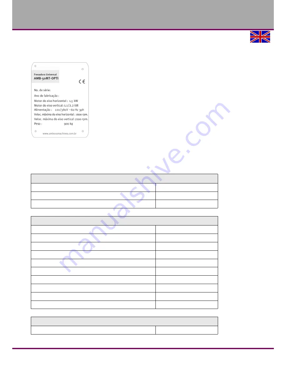
Type plate

Fig. 2-1:

Type plate

The following information are the dimensions and indications of weight and the manufacturer‘s 

approved machine data.

2.2

Electrical connection

z

H

0

6


~


V

0

8

/3

 220 

W

K


5

.

4

d

a

o

d

e

t

c

e

n

n

o

c

 l

a

t

o

T

W

k


5

.

1

e

l

d

n

i

p

s

 l

a

t

n

o

z

ir

o

h

 r

e

w

o

p

 r

o

t

o

M

Motor power vertical 

W

k


2

.

2


1

.

1

e

l

d

n

i

p

s

2.3

Dimensions

0

4


K

S

)

g

n

ill

i

m

 l

a

c

it

r

e

v

 ,

g

n

il

li

m

 l

a

t

n

o

z

ir

o

h

t

a

e

s


e

l

d

n

i

p

S

m

m

0

4

2


x


m

m

0

0

8

e

l

b

a

s

s

o

r

C

Height

2270 mm

Width

1500 mm

Depth

2100 mm

g

k


0

0

9

t

h

g

i

e

w

 l

a

t

o

T

g

k


0

5

0

1

g

n

i

g

a

k

c

a

p


g

n

i

d

u

l

c

n

t

h

g

i

e

W

m

m

0

0

1

2


x


0

2

2

1


x


0

9

2

1

H


x


W


x


L


g

n

i

g

a

k

c

a

p

 f

o


s

n

o

i

s

n

e

m

i

D

g

k


0

6

1

e

l

b

a

s

s

o

r

c

 f

o


d

a

o

.

x

a

M

4

 /


m

m

4

1

r

e

b

m

u

n

 /


e

z

i

s

 t

o

l

s

-

T

2.4

Adjustment travels/ Slewing ranges/ Distances

m

m


0

2

1

e

k

o

rt

s


e

l

d

n

i

p

S

Summary of Contents for AMB-50MT-OPTI

Page 1: ...GB Operating instructions Milling machine Version 1 1 1 AMB 50MT OPTI...

Page 2: ...button 13 1 8 3 Milling table 13 1 9 Safety check 14 1 10 Personnel protective equipment 14 1 11 Safety during operation 15 1 12 Safety during maintenance 15 1 12 1 Disconnecting and securing the mil...

Page 3: ...et milling head to the zero position 35 4 10 Move cross table up and down 35 4 11 Move spindle head carrier backwards and forwards 35 4 12 Move cross table to the left right X axis 36 4 12 1 Manual mo...

Page 4: ...lling table 76 9 3 Schaltgetriebe Vertikalfr sen Transmission gear vertical milling 77 9 4 Riementrieb Horizontalfr sen Belt drive horizontal milling 78 9 5 Universal Schwenkkopf Universal swiveling h...

Page 5: ...ention the prohibition warning and mandatory signs as well as the warning labels on the milling machine When installing operating maintaining and repairing the milling machine it is necessary to obser...

Page 6: ...severe injury of death to the staff WARNING Risk A danger that might cause severe injury to the staff or can lead to death CAUTION Danger of unsafe procedure that might cause injury to the staff or p...

Page 7: ...an be used as chip and spray guard The table housing does not possess any safety relevant function If required it is possible to disassemble the table housing If the milling machine is used in any way...

Page 8: ...amping tool such as e g clamping jaws WARNING Risk of injury caused by workpieces flying off Clamp the workpiece in the machine vice Make sure that the workpiece is firmly clamped in the machine vice...

Page 9: ...and tools with electrical voltages and currents We have used construction resources and safety techniques to minimize the health risk for the staff resulting from these hazards If the milling machine...

Page 10: ...isks in case of improper behaviour Any tasks which need to be performed beyond the operation in the standard mode must only be performed by the operator if it is indicated in these instructions and if...

Page 11: ...instructions require staff to confirm participation in training instructions by means of a signature check whether the staff is working safety and risk conscious and observes the operating instruction...

Page 12: ...the safety device or if it is not functioning for any reason It is your responsibility If a safety device has been activated or has failed the milling machine must only be used if you have removed the...

Page 13: ...tch is switched off In the position 0FF the lockable main switch can be secured against acciden tal or non authorized switching on by means of a padlock When the main switch is switched off the curren...

Page 14: ...t Protect your face and eyes wear a safety helmet with facial protection when performing works where your face and eyes are exposed to hazards Use protective gloves when handling pieces with sharp edg...

Page 15: ...the milling machine until the machine completely stopped moving Use the prescribed personnel protective equipment Wear close fitting clothes and a hairnet if required Do not use protective gloves when...

Page 16: ...work and re install them once the work has been completed This includes Covers Safety indications and warning signs Earth ground connections If you remove protective or safety devices re fit them imme...

Page 17: ...o t o M Motor power vertical W k 2 2 1 1 e l d n i p s 2 3 Dimensions 0 4 K S g n i l l i m l a c i t r e v g n i l l i m l a t n o z i r o h t a e s e l d n i p S m m 0 4 2 x m m 0 0 8 e l b a t s s...

Page 18: ...n i m 5 1 1 g n i l l i m l a c i t r e v d e e p s e l d n i p S 1 1 750 min 1 8 g n i l l i m l a c i t r e v s e g a t s r a e G n i m 8 5 g n i l l i m l a t n o z i r o h d e e p s e l d n i p S...

Page 19: ...noise disturbance it is not possible to use it reliably to determine if further precaution measures are required or not The following factors influence the actual degree of the noise exposure of the...

Page 20: ...r load can cause severe injuries or even death Check that the lifting and load suspension gear has sufficient load capacity and that it is in perfect condition Observe the accident prevention regulati...

Page 21: ...g a spirit level Check if the underground is sufficiently stable and rigid Total weight on page 18 ATTENTION If the underground is insufficiently rigid it may result in overlaying of vibrations betwee...

Page 22: ...wn on page 36 Alternatively it is possible to lift the Milling machine by means of a sling as displayed in Abbildung 3 1 The cross table has to be completely travelled to the machine stand The spindle...

Page 23: ...f required use anti vibratory feet refer to machine accessory SE1 SE2 Item No 3381012 3381016 for the mounting foot Align the Milling machine with a machine spirit level Check the alignment of the mac...

Page 24: ...ine by inexperienced staff you endanger people and the machine We do not take any liability for damages caused by incorrectly performed commissioning 3 5 1 Cleaning and lubricating Remove the anti cor...

Page 25: ...ing level of the gear oil The Milling machine is delivered with gear oil Check the filling levels of the gear vertical milling and of the infeed of the X axis If required fill the tank of the gear wit...

Page 26: ...of any failure in operation and make sure that it can not be started up accidentally or without authorization Notify the person responsible immediately of any modification Safety during operation on...

Page 27: ...FF The push button OFF switches off the rotation of the spindle Push button spindle Anti clockwise rotation The push button switches on the rotation of the spindle Horizontal milling Push button spind...

Page 28: ...ush button Close the spindle protection INFORMATION The control can be switched on only when all actuators such as the feed lever is in neutral position Switch the control on Press the push button Sta...

Page 29: ...the V belts ATTENTION Make sure that the V belt has the right tension If the V belt is tensed too strong or too weak it might result in damages The V belts are well tensed if it is possible to push it...

Page 30: ...February 25th 2013 Page 30 Original operating instructions MT50 GB 4 6 2 Speed table horizontal milling Use an open end wrench in order to be able to open the cover Fig 4 4 Speed table horizontal mil...

Page 31: ...hanging the speed using the gear switch On the drilling milling head there are two levers to switch over the gear to the desired spindle speed The speeds indicated in the table are resulting from the...

Page 32: ...Steel 10 25 m min Grey cast iron 10 22 m min Al alloy hardened 150 350 m min Speed min 1 3 8 1 3 4 6 3 1 0 0 2 1 9 7 2 2 1 9 5 3 5 8 7 2 4 9 1 1 5 7 1 0 8 9 9 1 0 8 0 4 6 7 4 2 1 6 0 1 6 5 1 1 7 7 7...

Page 33: ...ing emulsion as coolant procured from the specialised trade Make sure that the coolant is properly absorbed Respect the environment when disposing of any lubricants and coolants Follow the manufacture...

Page 34: ...m the gear Therefore we recommend to slew the milling head only as far as no oil escapes while the vertical spindle is running INFORMATION The gear of the milling machine is located in open reservoirs...

Page 35: ...indicator gauge Clamp the nuts again 4 10 Move cross table up and down Manual movement of the Z axis The height adjustment of the cross table is performed by means of a crank handle Release clamping l...

Page 36: ...options to move the cross table into the X direction By turning the crank handle at the front of the table Using the automatic table feed 4 12 1 Manual movement of the X axis In order to manually mov...

Page 37: ...ble and the operating mode Rapid mode or Feed are selected by means of the selection lever The movement is performed by means of the direction lever ATTENTION When the table feed speed is modified the...

Page 38: ...Move cross table forwards backwards Y axis Release clamping lever Engage the crank handle into the coupling by pressing Crank the cross table to the desired position Fig 4 17 Move the cross table in Y...

Page 39: ...far first move the spindle head completely to the front in order to be able to pass the arm of the control panel while slewing Fig 4 10 Move spindle head carrier backwards and forwards on page 37 Rele...

Page 40: ...e side milling cutters to the desired position of the milling spindle Determine the position of the slide bearing Fig 4 19 Milling spindle horizontal milling Fix the milling spindle by means of the dr...

Page 41: ...erefore if required release the clamping screws by slightly turning the spindle head carrier before plug in in the counterbearing Retighten the clamping screws after plugging them in Fig 4 18 Turn spi...

Page 42: ...ith a suitable cooling lubricant ensures better working results and a longer durability of the cutting tools Adjust the rate of flow by means of the stop and dosing valve ATTENTION Failure of the pump...

Page 43: ...s Fig 5 1 DPA 2000 5 2 The position display at the rear Fig 5 2 Position display rear Signal selection for input signal Top Sinus 11uAp p signal Bottom TTL square wave signal The setting is depending...

Page 44: ...oordinate axis the indicator light is positioned on the left of it 5 t u p n i c i r e m u n e h t o T s y e k c i r e m u N 6 Decimal point linear operat ing speed Setting key To input the decimal po...

Page 45: ...uting the holes along the inclined line The adding function of the calculator or holes distributing along the inclined line 19 Key for subtraction distrib uting the holes on the circle The subtraction...

Page 46: ...28 Tool 6 key To display the data coordinates of the tool 6 the indicator light is positioned above 29 Tool 7 key To display the data coordinates of the tool 7 the indicator light is positioned above...

Page 47: ...nstructions GB 6 Digital earthing DGND Blue Tachometer photoelectric switch power supply minus Outer switch shared cable 7 Little speed status LIN Yellow Outer switch low speed signal 9 Analogue earth...

Page 48: ...testing during this process the LED shows the following A The serial number of the position display B Company name C Software version after completing the self test the position display switches over...

Page 49: ...set the display value of the current position Example Preset the current position on the X axis at 12 324 Proceeding when machining Go back to the standard display mode Press the key in order to selec...

Page 50: ...ard display mode Press the key the mi display light is illuminated I e the function mode is Milling machine Press the key the mi display light is off I e the function mode is Lathe When you are in the...

Page 51: ...order to create the data coordinates for the tool 2 X 1 000 Y 2 000 Proceeding Go back to the standard display mode Press the key select the tool 2 the display light on the key is illuminated Press th...

Page 52: ...ver the display mode Remark When the position display is in a mode you cannot switch over You first have to go back to the standard display mode When the display light of the key is illuminated it mea...

Page 53: ...s the key the display light REF is no longer illuminated and the standard display mode is displayed again Remark During the entry of digits the display light beside the key is illuminated In order to...

Page 54: ...ctions are executed when the position display is in the function milling the display light milling is illuminated and in the standard display mode 6 12 Plunging hole along the inclined line function I...

Page 55: ...the key several times the coordinate layer changes according to the following sequence In order to change from the XY coordinate layer to the YZ layer In order to change from the YZ coordinate layer...

Page 56: ...rupt the function and return to the standard display except for the above mentioned cases Remark When you are in the status of the subdivided hole along the inclined line of the subdivided hole on the...

Page 57: ...e display at the top right displays and indicates that you can enter the coordinates for the position of the centre The XY coordinate layer is the standard layer The position of the current coordinate...

Page 58: ...f the angle of the starting point and press the key to confirm your entry The display at the top right displays and indicates that you can enter the value of the angle of the end point The LEDs on the...

Page 59: ...eg ments which are machined and the X axis along the positive direction on the YZ layer an inclination between these points and the Y axis along the positive direction Proceeding I Entering parameters...

Page 60: ...k to the standard display In the mode machining inclined line press the key in order to interrupt this function and to go back to the standard display except for the above described cases 6 15 Arc mac...

Page 61: ...dicate the last entry radius value of the arc The new entered value is displayed with the LEDs on the Y axis Enter the arc radius and press the key to confirm your entry The display at the top right d...

Page 62: ...coordinate axis and the display light of this axis is illuminated Enter the new coordinate values Press the key to confirm your entry Repeat the above mentioned three steps in order to complete the en...

Page 63: ...machining of the whole arc is competed Press the key in order to select the following point and the reference sequence number increases When the sequence number of the point equals the calculated maxi...

Page 64: ...g direction Press the digit keys the key and the key in order to enter the new programming values Parameters When there is no modification for the displayed parameter skip this step Press the key to s...

Page 65: ...solution of the Z axis Axes X Z 0 Y Z No of the parameter Resolution P 13 P 14 P 15 5 m 50 50 50 2 0 2 0 2 0 2 m 10 0 0 1 0 0 1 0 0 1 m 1 0 1 0 1 0 1 m Parameter Description P 16 The linear error comp...

Page 66: ...maximum nominal value can amount to 3 000 and the mini mum nominal value can amount to 30 When the first switch for the signal of the first stage is activated the posi tion display indicates the main...

Page 67: ...axis for the 2 axis position display displays the nominal value of the output maximum workpiece diameter Enter the new nominal value of the output maximum workpiece diameter Unit mm Press the key to...

Page 68: ...e operation long service life of the milling machine and the quality of the products to be manufactured Also devices and equipment from other manufacturers have to be in good order and condition 8 1 S...

Page 69: ...starting the machine Safety check on page 15 WARNING Before starting the milling machine you must check that ther e is no danger for persons and that the milling machine is not damaged 8 2 Inspection...

Page 70: ...s such as slide guideways feed spindles spindle nuts have to be lubricated with oil in regular intervals Always slightly oil blank surfaces Lubricate lifting spindle of the cross table with rolling be...

Page 71: ...T50 GB Start of work after every maintenance or repair work Spindle gear Vertical milling Oil level control The oil level must at least attain the centre resp top marking of the oil sight glass Fig 8...

Page 72: ...ve the spindle run for a few minutes the oil will heat up and easily penetrate from the opening Unscrew the screw from the drain hole Fig 8 6 Drain hole vertical gear Unscrew the screw from the filler...

Page 73: ...e wipers in order to attain the readjusting screws of the corresponding V ledges Turn the readjusting screws clockwise using a screw driver until it is only possible to move the guideway only slightly...

Page 74: ...e company Optimum Maschinen Germany GmbH does not take any responsibility nor does it guarantee against damages and operating malfunctions resulting from failure to observe these operating instruction...

Page 75: ...Version 1 1 1 vom 25 Februar 2013 Seite 75 Originalbetriebsanleitung MT50 D 9 Ersatzteile Spare parts 9 1 S ule und Fu Column and Base Abb 9 1 Column and Base...

Page 76: ...Version 1 1 1 vom 25 Februar 2013 Seite 76 Originalbetriebsanleitung MT50 D 9 2 Fr stisch Milling table Abb 9 2 Fr stisch 1 5...

Page 77: ...Version 1 1 1 vom 25 Februar 2013 Seite 77 Originalbetriebsanleitung MT50 D 9 3 Schaltgetriebe Vertikalfr sen Transmission gear vertical milling Abb 9 3 Schaltgetriebe...

Page 78: ...Version 1 1 1 vom 25 Februar 2013 Seite 78 Originalbetriebsanleitung MT50 D 9 4 Riementrieb Horizontalfr sen Belt drive horizontal milling Abb 9 4 Vorschubgetriebe 2 4...

Page 79: ...Version 1 1 1 vom 25 Februar 2013 Seite 79 Originalbetriebsanleitung MT50 D 9 5 Universal Schwenkkopf Universal swiveling head Abb 9 5 Universal Schwenkkopf...

Page 80: ...atzteilnummer zusammengesetzt aus 0 Artikel nummer Positionsnummer Bestellmenge When ordering spare parts the items specified below will be considered Machine name year of construction spare part numb...

Page 81: ...Version 1 1 1 dated Februar 25th 2013 Page 81 Original operating instructions MT50 GB 10 Wiring diagram...

Page 82: ...Version 1 1 1 dated Februar 25th 2013 Page 82 Original operating instructions MT50 GB...

Page 83: ...e the tool Have the bearing replaced on the spindle head Correctly clamp the tool Replace the clamping chuck It is not possible to insert the taper into the spindle sleeve Remove dirt grease or oil at...

Page 84: ...orking spindle does not move up and down Readjusting ledge is loose Loose clamping chuck Tool is blunt Tool is not fixed Readjust bearing clearance or replace bearing Readjust bearing play fixed beari...

Page 85: ...nts wrongly the displayed dis tance does not comply with the actual distance 1 Make sure that the machine tool and the cover of the position display are cor rectly earthed 2 Inaccuracy of the machine...

Page 86: ...play 1 Make sure that the machine tool and the cover of the position display are cor rectly earthed 2 Make sure that the shielding cable between the reader and the metal cover are connected correctly...

Page 87: ...f the tool holder cone of the drill of the drill chuck Workpiece Piece to be milled drilled or machined Draw in rod Threaded rod to fix the taper mandrel in the spindle sleeve Drill chuck Drill bit ch...

Page 88: ...B 13 4 Product follow up We have a follow up service for our products which extends even after shipment We would be grateful if you could send us the following information Modified settings Experience...

Page 89: ...and warranty claims Using the product beyond the technical options and proper use in particular due to overstraining of the machine Any defects arising by one s own fault due to faulty operations or i...

Page 90: ...l recycling The packaging wood can be supplied to the disposal or reuse It is possible to crush any packaging material made of cardboard and supply it to the waste paper collection The films are made...

Page 91: ...up used coolant emulsions and oils since only used oils which had not been mixed up are recyclable The disposal advices for the used lubricants are made available by the manufacturer for lubricants I...

Page 92: ...alfunctions 89 Position display 91 Mechanical maintenance work 17 Milling head Set zero position 36 O Obligations operating company 12 operator 12 Operating material 19 P Personnel protective equipmen...

Page 93: ...Version 1 1 1 dated February 25th 2013 Page 93 Original operating instructions MT50 GB...

Reviews: