18
EN
• The stabilized value on the display (F) is read as
the actual reading.
• Press the
MODE
button (H) to change the
measurement mode. The set measurement
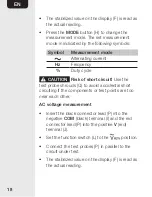
mode in indicated by the following symbols:
Symbol
Measurement mode
Alternating current
Hz
Frequency
%
Duty cycle
CAUTION
Risk of short circuit!
Use the
test probe shrouds (Q) to avoid accidental short
circuiting if the components or test points are too
near each other.
AC voltage measurement
• Insert the black connector lead (P) into the
negative
COM
(black) terminal (I) and the red
connector lead (P) into the positive
V
(red)
terminal (J).
• Set the function switch (L) to the
position.
• Connect the test probes (P) in parallel to the
circuit under test.
• The stabilized value on the display (F) is read as
the actual reading.


