TM 9-2320-283-20-3
STEERING SYSTEM.
3-217. STEERING ARM MAINTENANCE (Continued).
LOCATION/ITEM
ACTION
REMARKS
D. INSTALLATION (Continued).
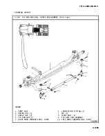
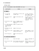
4. Castle nut (14) steering arm cot-
ter pin hole (22).
5. Cotter pin (13).
6. Castle nut (7) and drag link cotter
pin hole (23).
7. Cotter pin (6).
Install and secure.
Torque castle nut.
Torque to minimum of 360
lb-ft (488 N•m). Using
torque wrench, continue to
tighten nut (14) to align
with steering arm cotter
Install and secure.
pin hole (22).
Tighten castle nut.
Torque to minimum of 115
lb-ft (156 N•m). Using
torque wrench, continue to
tighten nut (7) to align with
drag link cotter pin hole
(23).
Change 1 3-1303
Summary of Contents for M915A1
Page 10: ......
Page 17: ......
Page 59: ......
Page 130: ......
Page 155: ......
Page 378: ...TM 9 2320 283 20 3 CAB AND BODY 3 264 OUTSIDE FRONT HANDLE REPLACEMENT Continued 3 1551...
Page 622: ...TM 9 2320 283 20 3 GAGES NONELECTRICAL 3 309 TACHOGRAPH REPLACEMENT Continued TA 237846 3 1795...
Page 669: ......
Page 673: ......
Page 705: ......
Page 707: ......
Page 717: ......
Page 737: ......
Page 738: ......
Page 739: ......
Page 740: ......
Page 741: ......
Page 742: ......
Page 743: ......
Page 744: ......
Page 745: ......
Page 746: ......
Page 748: ......
Page 756: ...PIN 054576 000...


