background image

Page 6

AM-64x DAT High Capacity Tape Drives

PDI-00649-00, A01

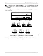
SCSI ID #0

SCSI ID #1

SCSI ID #2

SCSI ID #3

SCSI ID #4

SCSI ID #5

SCSI ID #6

The two outside pins (shown in gray) are used to
select SCSI-1 or SCSI-2. With the jumper removed,
the drive is configured for SCSI-2; with the jumper
installed the drive is configured for SCSI-1. For all
Alpha Micro configurations, the drive must be
configured for SCSI-2 operation.

DC POWER

PIN-1

KEYED
CONNECTOR

Figure 3 - AM-648 (Exabyte) Configuration

Summary of Contents for AM-647

Page 1: ...PDI 00649 00 A01 AM 647 648 649 Digital Audio Tape DAT High Capacity Tape Drives Installation Instructions ...

Page 2: ...d by the manufacturer Discard used batteries according to the manufacturer s instructions ATTENTION Il y a danger d explosion s il y a replacement incorrect de la batterie Remplacer uniquement avec une batterie du même type ou d un type recommandé par le constructeur Mettre au rébut les batteries usagées conformément aux instructions du fabricant For AM 6000 systems replace batteries with Panasoni...

Page 3: ...MOUNT AND PEDESTAL COMPUTERS 13 Front Bezel Removal and Modification 14 Building and Installing the DAT Drive Mounting Assembly 14 Power and Interface Cables 18 DAT INSTALLATION AM 1400 AND AM 1600 DESKTOP COMPUTERS 19 DAT INSTALLATION AM 990 COMPUTERS 21 SOFTWARE INFORMATION FOR DAT DRIVES 22 OPERATING SOFTWARE MINIMUM FILE VERSIONS 23 COPYING THE GENERIC DEVICE DRIVER 24 MODIFYING THE SYSTEM INI...

Page 4: ... Narrow 11 Figure 8b External SCSI Terminator Wide 11 Figure 9 Drive Mounting Assembly 15 Figure 10 Plastic Mounting Base 16 Figure 11 Metal Top Support Bracket 17 Figure 12 Securing the Drive Assembly to the Front Bezel 18 Figure 13 AM 1400 1600 Drive Mounting Bracket 19 Figure 14 AM 1400 1600 Drive Mounting Assembly 20 Figure 15 Peripheral Mounting Rail 21 Figure 16 Attaching Mounting Rails to P...

Page 5: ... for help PRODUCT DESCRIPTIONS This manual covers several different DAT tape drives for use in various Alpha Micro computers Cable connections software installation and use are essentially the same for all DAT drives However each DAT has certain unique operational characteristics Common Characteristics Can be mounted in any 5 25 configuration Must be attached to the system SCSI bus Use 4mm magneti...

Page 6: ...S non compressed mode and approximately 4 gigabytes in DDS DC compressed mode with a 90 meter tape The AM 649 01 8 gigabyte drive HP model C1533A or C1599A has the same data capacities as the AM 649 00 using DDS DDS 1 tape with additional DDS 2 capabilities yielding approximately 4 gigabytes of storage in native DDS 2 mode and 8 gigabytes in DDS 2 DC compressed mode when used with 120 meter DDS 2 ...

Page 7: ...computer uses a SCSI bus you have seven SCSI IDs to choose from 0 through 6 The SASI bus supports only SCSI IDs 0 through 3 Don t worry if you have a gap in your device addressing AMOS doesn t require that each device be defined in sequence Except for systems with a CMOS configuration menu such as the Eagle 550 and Roadrunner 060 if you want to be able to warm boot from your DAT drive you must set...

Page 8: ... BASED COMPUTERS SWITCH 5 WLL ALWAYS BE SET TO THE OFF OR DISABLED POSITION SERIES 90 PRODUCTS WILL SET SWITCH 5 TO THE ON OR ENABLED POSITION JP4 JP4 IN DRIVE SUPPLIES TERMINATION POWER TO THE SCSI BUS JP4 OUT DRIVE DOES NOT SUPPLY TERMINATION POWER TO THE SCSI BUS SWIITCH 4 IN THE OFF POSITION SCSI 1 SWITCH 4 IN THE ON POSITION SCSI 2 O F F 1 2 3 O F F 1 2 3 O F F 1 2 3 4 5 6 Leave switches 6 7 ...

Page 9: ...O THE OFF OR DISABLED POSITION SERIES 90 PRODUCTS WILL SET SWITCH 5 TO THE ON OR ENABLED POSITION SWIITCH 4 IN THE OFF POSITION SCSI 1 SWITCH 4 IN THE ON POSITION SCSI 2 O F F 1 2 3 O F F 1 2 3 O F F 1 2 3 4 5 6 Leave switches 6 7 and 8 set as shown in the illustration 1 2 3 4 5 6 7 8 O F F TERMINATORS TERMINATION POWER JUMPER 0UT TERMINATION POWER DISABLED IN TERMINATION POWER ENABLED PIN 1 Figur...

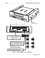
Page 10: ...o outside pins shown in gray are used to select SCSI 1 or SCSI 2 With the jumper removed the drive is configured for SCSI 2 with the jumper installed the drive is configured for SCSI 1 For all Alpha Micro configurations the drive must be configured for SCSI 2 operation DC POWER PIN 1 KEYED CONNECTOR Figure 3 AM 648 Exabyte Configuration ...
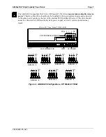
Page 11: ...ply as the rest of the internal SCSI peripheral devices This drive should never be connected to a different subsystem power supply as erratic system operation may result SCSI 2 1 0 NC 2 1 0 NC SCSI I D 0 2 1 0 NC SCSI I D 1 2 1 0 NC SCSI I D 2 2 1 0 NC SCSI I D 4 2 1 0 NC SCSI I D 5 2 1 0 NC SCSI I D 6 2 1 0 NC SCSI I D 3 SCSI CONNECTOR DC POWER PIN 1 SCSI ADDRESS JUMPERS HP 4mm DAT Drive Model C1...

Page 12: ...SI 2 SCSI 1 SCSI 0 NC TERM PWR SCSI I D 2 SCSI 2 SCSI 1 SCSI 0 NC TERM PWR SCSI I D 1 SCSI 2 SCSI 1 SCSI 0 NC TERM PWR SCSI I D 0 SCSI 2 SCSI 1 SCSI 0 NC TERM PWR SCSI I D 4 SCSI 2 SCSI 1 SCSI 0 NC TERM PWR SCSI I D 5 SCSI 2 SCSI 1 SCSI 0 NC TERM PWR SCSI I D 6 SCSI 2 SCSI 1 SCSI 0 NC TERM PWR HP 4mm DAT Drive Model C1533A C1599A 8 GB Figure 5 AM 649 01 Configuration HP Model C1533A C1599A The AM ...

Page 13: ...ing is switches 4 8 set to on Figure 6 AM 649 00 and 01 Configuration Option Switches SCSI BUS TERMINATION To function properly the SCSI bus on your computer must be terminated at each end of the cable The SCSI controller terminates one end of the bus the opposite end of the bus can be terminated in one of two ways 1 using the preferred method an external terminator or 2 installing on board termin...

Page 14: ...ke a portable CD ROM drive eliminating the need to remove terminators from a SCSI device inside the computer As computer performance increases the SCSI bus becomes more sensitive to termination issues Newer AMOS computers such as the AM 6000 require active termination of the SCSI bus Check your computer Owner s Manual to make sure you are terminating the SCSI bus properly External terminators are ...

Page 15: ...ble DWB 10200 01 The connector on this cable is compatible with the external terminator and also allows you to easily attach a portable CD ROM drive or other SCSI device The figures below show both narrow and wide SCSI terminators SCSI BAIL LOCKS Figure 8a External SCSI Terminator Narrow PRA 00222 20 EXTERNAL SCSI BUS TERMINATOR SCSI CONNECTOR ON BACK PANEL Figure 8b External SCSI Terminator Wide ...

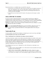
Page 16: ...rmination enabled your system will probably perform erratically This is true whether the last device is in the computer chassis or in a subsystem chassis Termination Power In order to properly control SCSI bus termination a termination power source must be provided this is especially important when using an external terminator Why is Termination Power so important when using an external terminator...

Page 17: ... boards with termination power enabled See the Roadrunner installation instructions for information on how to configure the termination power jumper For information on how to configure terminator power on SCSI hard disk and magnetic tape peripherals see the following documents Each SCSI disk drive shipped by Alpha Micro has a one page notice with jumper configuration information including instruct...

Page 18: ...the front bezel to the computer s chassis 4 Follow the bezel modification instructions included with your installation kit then reinstall the bezel on your computer 5 Don t forget to plug the display panel cable back into your CPU board Building and Installing the DAT Drive Mounting Assembly The DAT drive mounting assembly is the same for both pedestal and rack mount computers The assembly consist...

Page 19: ...ng holes in the plastic mounting base Align the screw holes on the drive with the proper holes marked as A in Figure 10 in the plastic mounting base Make sure the drive s front panel is pointed in the direction indicated by the arrow in Figure 10 3 Install the two screws included in the mounting kit that hold the plastic mounting base to the drive If you are installing a diskette drive or a 1 4 st...

Page 20: ...GNETIC TAPE DRIVE or ANY 5 1 4 FULL HEIGHT SCSI HARD DISK DRIVE ANY 5 1 4 HALF HEIGHT FLOPPY DISKETTE DRIVE or ANY 5 1 4 HALF HEIGHT SCSI HARD DISK DRIVE Figure 10 Plastic Mounting Base 6 Set the metal support bracket on top of the drive assembly as shown in Figure 9 Position the bracket so the mounting hole see Figure 11 aligns with the screw hole on the side top of the DAT drive and the screw ho...

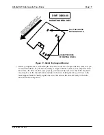
Page 21: ...t 7 Before you tighten the screw holding the DAT drive to the metal support bracket make sure you are satisfied with the way the drive assembly is aligned with the cutout in your computer s front bezel Once the drive or drives are properly positioned install the screw that holds the plastic mounting base to the chassis bottom and tighten the screw holding the drive or drives to the metal support b...

Page 22: ...ur computer On some computers the 50 pin SCSI interface cable has keyed connectors that insure a pin 1 to pin 1 connection with the DAT drive If your interface cable is not keyed be sure to use the colored stripe on the cable as a pin 1 reference If your computer uses the 68 pin Wide SCSI 2 bus you must use the appropriate 50 pin to 68 pin adapter to connect the DAT drive to the SCSI cable Plug th...

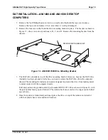
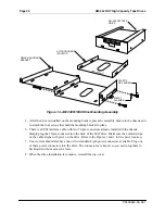
Page 23: ...re 13 AM 1400 1600 Drive Mounting Bracket 3 The DAT drive installs on top of the drive mounting bracket However because the DAT drive internally ties logic ground to its frame you need to isolate the DAT drive from the computer chassis The mounting kit includes an isolator designed to prevent the drive from making metal to metal contact with the computer chassis Fold and position the ground isolat...

Page 24: ...cket in place 6 There is a SCSI interface cable with two 50 pin connectors already installed in the chassis Simply plug the 50 pin connector into the back of the DAT drive Make sure the colored stripe on the cable aligns with pin 1 on the drive Refer to the Figures 1 and 2 for the pin 1 location 7 Your system should also have one or two standard 4 pin power connectors available Plug one of these p...

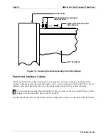
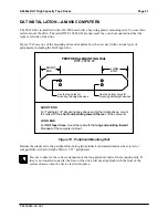
Page 25: ...t devices Use the bottom holes for mounting half height devices SHORT END For Tandberg 1 4 streaming tape drives and all hard disk drives mount the rails with the short end pointing toward the rear of the computer LONG END For DAT tape drives mount the rails with the long end pointing toward the rear of the computer cabinet Figure 15 Peripheral Mounting Rail Besides the plastic rails the periphera...

Page 26: ...everal points to remember when using DAT drives Depending on your system configuration it may be possible to support up to four DAT drives in the same system Also a DAT drive can be used with a Tandberg streaming tape drive DAT tape drives are not supported in S 100 bus computers or in AM 1000 1200 computers without a Roadrunner upgrade AM 647 drives must be used with AMOS 1 4 or 2 2 or later AM 6...

Page 27: ...your AMOS operating system AM 647 Minimum File Versions For AMOS 1 4 Systems For AMOS 2 2 Systems 647DVR DVR 647DVR DVR MTUSAV LIT 3 0 121 MTUSAV LIT 3 1 121 MTURES LIT 3 0 124 MTURES LIT 3 1 124 MTUDIR LIT 3 0 117 MTUDIR LIT 3 1 117 TAPSER LIT 3 0 115 TAPSER LIT 3 0 115 WRMGEN LIT 2 0 138 WRMGEN LIT 2 0 140 FWUPD LIT 1 0 100 FWUPD LIT 1 0 100 CRT620 LIT 2 0 112 CRT620 LIT 2 0 112 AM 648 and AM 64...

Page 28: ...I Then edit that copy using AlphaVUE or another text editor making the modifications described below NEVER modify the system initialization command file directly Always make your changes in a copy of the file When you have finished use MONTST to test the new file If the MONTST is successful you can then copy the test initialization file to AMOSL INI or AMOS32 INI as applicable If it fails you can ...

Page 29: ...ommand File TESTING THE INITIALIZATION FILE When you re done editing the TEST INI file save the file and exit from the text editor With the new DAT drive installed and its address jumpers and terminators set properly log into OPR make sure no one else is using the computer and use MONTST to test the TEST INI file When your computer executes the DEVTBL DAT0 statement it will display information sim...

Page 30: ...r DAT drive when your system contains one of the CPU boards listed below However your boot PROMs must meet the revision requirements in the applicable table Boot PROMS for AM 647 DAT Drives CPU Board PROM Revision AM 134 XX A00 AM 135 XX A00 AM 140 A00 AM 145 B02 AM 175 G02 AM 180 D02 AM 185 A01 AM 185 50 A00 The following table applies to all AM 648 and AM 649 00 drives and AM 649 01 drives label...

Page 31: ...tor cannot exceed 200KB If you exceed the 200KB limit WRMGEN generates an overflow error When WRMGEN prompts you for the system disk driver and SCSI dispatcher name enter the appropriate generic SCSI driver and simple SCSI dispatcher for your computer if you aren t sure what driver to use please refer to your computer Owner s Manual For example for an AM 6000 these entries would be SCZR60 DVR and ...

Page 32: ...o SYSTEM MEMORY one per line Enter blank to terminate loading Program to load SYSMSG USA RETURN Program to load DAT DVR 1 6 RETURN Program to load CMDLIN SYS RETURN Program to load SCNWLD SYS RETURN Program to load RETURN Enter name of program s to be preloaded into USER PARTITION one per line Enter blank to terminate loading Program to load MOUNT LIT RETURN Program to load LOG LIT RETURN Program ...

Page 33: ...l for more details on modifying the CMOS configuration When you use CRT620 to create a warm boot tape the tape can include only the necessary programs and drivers to perform a warm boot and be minimally operational You cannot save any data files to the tape RUNNING SELF TEST Now that the DAT drive has been installed and your system is up and running you may want to run the system self test to be s...

Page 34: ... the predefined DDS error threshold A new tape should be used for future writes and or the tape heads should be cleaned with an approved DDS cleaning cassette Otherwise operation is proceeding normally This signal is a warning only If the green LED is flashing rapidly this indicates the tape could not be written to correctly maximum rewrite count exceeded The WRITE operation failed and you should ...

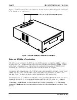
Page 35: ...ning the power off and then back on again AM 649 DAT DRIVE STATUS LEDS The front panel of the AM 649 DAT drive has two status LEDs The green LED indicates normal tape functions The amber LED indicates clean attention warnings The various LED displays have the following meanings TAPE EJECT STATUS LEDS GREEN AMBER Figure 20 AM 649 DAT Drive Faceplate Green LED slow flashing Amber LED off Activity lo...

Page 36: ...by mechanically pulling the tape cartridge into the load position just like your home VCR 3 Once the tape is loaded the status LEDs indicate the status of both the drive and the cassette 4 Use the MTUSAV command to copy a few files onto a blank tape cartridge and then use MTURES to restore them into a different disk account or onto another logical disk Use MTUDIR to list the files stored on the ta...

Page 37: ...AM 64x DAT High Capacity Tape Drives Page 33 PDI 00649 00 A01 WINDOW SHUT WRITE ENABLE WINDOW OPEN WRITE PROTECTED TAPE EJECT BUTTON DRIVE STATUS LEDs DAT Figure 21 Loading a DAT Tape Cartridge ...

Page 38: ...ssed mode Tapes created in non compressed DDS mode can be interchanged between other Alpha Micro 4mm DAT drives The TMODE command allows you to switch between compressed and non compressed write modes The program will display the currently set data format and the available write options when you enter the TMODE command with the device name For example TMODE DAT0 RETURN Recording format DDS DC comp...

Page 39: ...aning cassette is used it advances to an unused portion of the tape Eventually the entire tape is used up If the cleaning cartridge does not automatically eject the cleaning portion of the tape has been used up Press the unload button to eject the cleaning cartridge and discard it Do not use an audio DAT cleaning cassette It will not be properly recognized by your DAT tape drive TAPE FORMATS USAGE...

Page 40: ...d them and set itself up accordingly Older DDS tapes are identical to DDS 1 tapes with the exception that the newer DDS 1 tapes have the MRS stripes and the older DDS tapes do not Both DDS and DDS 1 tapes work equally well in the DDS DC data compression mode DAT drives with MRS must have the MRS disabled in order to write to the older DDS tapes If the MRS does not recognize the tape it defaults to...

Page 41: ...0 GB and 120 meter tapes written DDS 2 DC compressed mode yield a capacity of approximately 8 0 GB DDS 2 mode also has considerably faster file access and data transfer rates ADDITIONAL DOCUMENTATION There are a number of other documents in the Alpha Micro documentation library that amplify the concepts discussed in this document Your primary reference source should be your computer Owner s Manual...

Reviews: