6
Subject to technical amendments without prior notice | 83055400iUK – 2.1 | ait-deutschland GmbH
9. If necessary, install additional external cables.
Instruction manual for your appliance, “Connection layout”
and “Circuit diagrams” for your appliance type
NOTE
The inputs and outputs on the motherboard are assigned
as shown on the device’s terminal connection diagram.
In addition, the assignment is shown on the inside of the
housing of the wall-mounted controller.
10. Place covers on the cable ducts. Swivel folding bracket of the
cable entry back into the initial position and allow to latch in-
to place below the fastening screw. Tighten fastening screw.
11. Put the housing cover back on and tighten the side fasten-
ing screws.
IMPORTANT
Route all lines that you connect to the heating and heat
pump control outside the heating and heat pump in a ca-
ble duct (necessary for strain relief; to be realised at the
customer).
IMPORTANT
The BUS communication cable must be laid at a spacing >
10 cm from other cables. Therefore, lay with the appropri-
ate spacing in a separate cable duct.
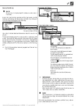
1 1~/N/PE/230V power supply (to the terminal block); cable
cross-section max. 2.5 mm²
2 other 230 V inputs (electricity outage , …)
3 Sensor cables including the TRL return sensor on the return
to the heat pump
4. Connect the BUS communication cable, which leads to the
heat pump, to terminal block X10 of the controller board.
Then route the BUS communication cable downwards and
through the cable ducts and through the cable entry to the
outside.
5. Connect the 230 V voltage supply line to the voltage supply
terminal block.
NOTE
The terminal block has spring-type terminals to maximum
2.5 mm2.
Insulate the cable jacket so that the jacket end is located
between the sealing lip and cable duct.
6. Connect the 230 V power supply for the outdoor unit to the
terminal block and route it downwards through the cable
ducts and through the cable entry to the outdoor unit out-
side.
7. Connect the PWM control signal for the circulation pump to
the terminal block X10.
8. A separately packed return sensor (TRL) with appropriate in-
stallation materials is enclosed with the air/water heat pump
for outdoor installation. Use cable ties and heat transfer com-
pound to fix the return sensor to the return (heat-conducting
pipe) to the heat pump as shown in the figure and connect
(to NTC8) as shown in the circuit diagram.
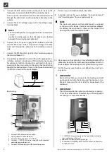
Basic wirng:
1 Connect BUS communication cable
2 Laying cables in the cable ducts
3 Connect TRL return sensor (on NTC8)
4 Connect 1~/N/PE/230 V power supply for wall-mounted
controller and outdoor unit
5 Connect PWM control signal for circulation pump


