40
Electronic Lock Cylinders of the PegaSys Series
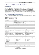
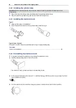
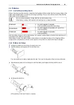
2.2.2 Installing the cylinder body
Important:
Before assembling the knob module, always check the freedom of movement of all
components.
Step 1:
Remove the fixing screw and dismantle the existing cylinder body.
Step 2
: Insert the cylinder body and secure it with the fixing screw.
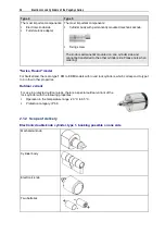
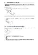
2.2.3 Installing the electronic knob
Type 1
Observe the notes on installation!
Insert the electronic knob into the cylinder body while turning it.
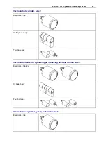
Type 2, type 3, type 4
For type 2, 3 and 4, the same workflows as for type 1 apply analogously.
See also
Notes on installation ............................................................................................................... 39
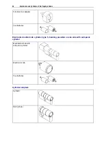
2.2.4 Dismantling the electronic knob
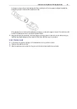
If required: Activate the electronics by turning the electronic knob.
Hold the disassembly card in front of the knob.
The electronic lock cylinder switches to disassembly mode.
In the case of hardware with version 2.1, 3-LED technology: With the suction cup, remove the front
cover (small cover plate).
Turn the electronic knob until the emergency power contacts are at the 9 o'clock position.
Summary of Contents for PegaSys
Page 2: ......
Page 4: ......
Page 7: ...Installation Instructions for PegaSys Electronic Door Fittings ...
Page 8: ......
Page 34: ......
Page 35: ...Installation Instructions for PegaSys Electronic Lock Cylinders ...
Page 36: ......
Page 52: ......
Page 53: ...Installation Instructions for PegaSys Electronic Locker Locks ...
Page 54: ......
Page 61: ...PegaSys Locker Locks 57 Locking lever type 4 6 5 mm angled ...
Page 63: ...PegaSys Teach In or NetworkOnCard Operation Valid for all PegaSys offline components ...
Page 64: ......
Page 78: ......
Page 83: ......

