10
2480 Remote Intensifier Tooling Alcoa Fastening Systems
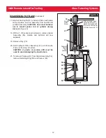
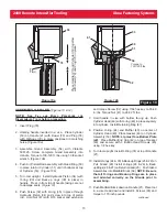
6. e.) Remove Piston Assembly Tool and Spacer
from Piston. Remove Rear Gland assembly
and Front Gland assembly. Remove Piston
Insertion Tool from Cylinder.
(Figure 2d)
f.) Use a small diameter dull pointed rod to
remove all O-rings and seals. Clean parts,
including O-ring grooves. Examine all
components for wear or defects. Replace
parts as required.
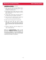
7. Disassemble Air Trigger and Hose Assembly as
follows:
(Figure 3)
NOTE: When removing Air Hose from either
fitting, slice hose lengthwise, at fitting, just
enough to remove easily. Then cut hose
squarely across to be ready for assembly.
a.) Remove Air Hose from Hose Fitting, and
unscrew Hose Fitting from Trigger Housing.
b.) Unscrew Air Trigger Assembly from Trigger
Housing. Pull Trigger Stem out of Trigger
Body, and remove O-rings from Trigger
Stem and Trigger Body.
Figure 2a
Figure 2b
Piston Assembly Tool
Spacer
Piston
Insertion
Tool
push Piston to full rearward position
Pintail
Deflector
End Cap
Figure 2c
Support
Press
Figure 2d
Rear Gland
Assembly
Front Gland
Assembly
Cylinder
112555
Trigger
Stem
500772
O-Ring
500777
O-Ring
112556
Trigger
Body
114887
Trigger
Housing
127537
Air Hose and
Trigger Assembly
124888
Air Hose
119345 Air Trigger Assembly
505741
Hose
Fitting
Figure 3


