background image

Americas

Alcoa Fastening Systems

Aerospace Products

Tucson Operations

3724 East Columbia

Tucson, AZ 85714

800-234-4825

520-747-9898

FAX: 520-748-2142

Alcoa Fastening Systems

Aerospace Products

Carson Operations

PO Box 5268

900 Watson Center Rd.

Carson, CA 90749

800-421-1459

310-830-8200

FAX: 310-830-1436

Alcoa Fastening Systems

Commercial Products

Waco Operations

PO Box 8117

8001 Imperial Drive

Waco,TX 76714-8117

800-388-4825

254-776-2000

FAX: 254-751-5259

Alcoa Fastening Systems

Commercial Products

Kingston Operations

1 Corporate Drive

Kingston, NY 12401

800-431-3091

845-331-7300

FAX: 845-334-7333

www.hucktools.com 

Alcoa Fastening Systems

Commercial Products

Canada Operations

6150 Kennedy Road, Unit 10

Mississagua, Ontario L5T2J4

Canada

905-564-4825

FAX: 905-564-1963

Alcoa Fastening Systems

Commercial Products

Latin America Operations

Avenida Parque Lira. 79-402

Tacubaya Mexico, D.F.

C.P. 11850

FAX: 525-515-1776

TELEX: 1173530 LUKSME

Far East

Alcoa Fastening Systems

Commercial Products

Australia Operations

14 Viewtech Place

Rowville,Victoria 

Australia  3178

03-764-5500

Toll Free: 008-335-030

FAX: 03-764-5510

Europe

Alcoa Fastening Systems

Commercial Products

United Kingdom Operations

Unit C, Stafford Park 7

Telford, Shropshire

England TF3 3BQ

01952-290011

FAX: 0952-290459

Alcoa Fastening Systems

Aerospace Products

France Operations

Clos D’Asseville

BP4

95450 Us Par Vigny

France

33-1-30-27-9500

FAX: 33-1-34-66-0600

A Global Organization

Alcoa Fastening Systems (AFS) maintains company

offices throughout the United States and Canada,

with subsidiary offices in many other countries.

Authorized  AFS distributors are also located in

many of the world’s 

industrial and Aerspace centers, where they provide

a ready source of AFS fasteners, installation tools,

tool parts, and application assistance.

For The Long Haul,The Future of Fastening Technology,
The Future of Assembly Technology,The Future of Tooling
Technology, and Tools of Productivity are service marks of Huck
International. Huck provides technical assistance regarding the use
and application of Huck fasteners and tooling.
NOTICE:The information contained in this publication is only for
general guidance with regard to properties of the products shown

and/or the means for selecting such products, and is not intended
to create any warranty, express, implied, or statutory; all warranties
are contained only in Huck’s written quotations,
acknowledgements, and/or purchase orders. It is recommended
that the user secure specific, up-to-date data and information
regarding each application and/or use of such products.

HWB898    

1003-5M

© 2003 Alcoa Fastening Systems
1 Corporate Drive, Kingston, NY 12401  • Tel: 800-431-3091 • Fax: 845-334-7333 • E-mail: [email protected] • www.alcoafasteningsystems.com

One Great Connection

SM

Alcoa Fastening Systems world-wide locations:

For the Long Haul

Summary of Contents for Huck 2480RI

Page 1: ...01 28 2005 HK1009 INSTRUCTION MANUAL 2480RI PNEUDRAULIC INSTALLATION TOOL...

Page 2: ...lace Kingston New York USA Date January 2005 Sound Levels Model 2480RI SEL 82 dB A peak value 108 2 dB C For an eight hour work day installing 5000 typical Huck fasteners will result in an equivalent...

Page 3: ...3 SPECIFICATIONS 4 SAFETY 5 TOOL DANGER ZONES 6 PRINCIPLE OF OPERATION 7 PREPARATION FOR USE 8 SERVICING THE TOOL General 8 Daily 8 Weekly 8 Disassembly 9 12 Assembly 13 16 Fill and Bleed 17 18 SERVIC...

Page 4: ...205 208 3 32 84 3 5 425 138 1 41 36 6 55 166 Stroke 875 500 without Stroke Limiter Weight 2 2 lbs Tool Head only Air Pressure 90 psi Pull Capacity 3946 lbs 90 psi Intensifier Displacement 8298526 cu...

Page 5: ...efer to ANSI Z87 1 1989 6 Disconnect primary power source before doing maintenance on Huck equipment 7 If any equipment shows signs of damage wear or leakage do not connect it to the primary power sup...

Page 6: ...6 2480 Remote Intensifier Tooling Alcoa Fastening Systems TOOL DANAGER ZONES...

Page 7: ...rod moves downward a column of pressurized fluid is forced into the tool which moves the pull piston back The attached nose assembly moves with the pull piston to start fastener installation When fast...

Page 8: ...tools both standard and special must be available 4 All parts must be handled carefully and examined for damage or wear Always replace Seals when tool is disassembled for any reason Components should...

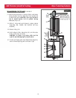
Page 9: ...r Piston 4 can be pushed to rear of Cylinder 12 to drain fluid Discard fluid 6 Disassemble cylinder and piston assembly as follows a Place Spacer over threaded end of Piston Figure 2a Thread Piston As...

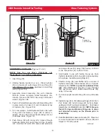
Page 10: ...itting just enough to remove easily Then cut hose squarely across to be ready for assembly a Remove Air Hose from Hose Fitting and unscrew Hose Fitting from Trigger Housing b Unscrew Air Trigger Assem...

Page 11: ...top of Manifold Block 10 Remove Pull Gland Assembly 90 and Return Gland Assembly 22 from the separated Handle and Manifold Block and remove seals from glands Figure 5 11 Hold remaining Handle and Cyl...

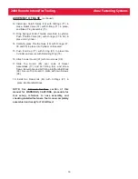
Page 12: ...nsion remove Gland Assembly 54 Handle and Cylinder will now separate 19 Remove Plug 78 20 Push hydraulic Piston Assembly 31 out of handle Push out from top to bottom CAUTION A plastic or wooden drift...

Page 13: ...ge may result 2 Thread Piston Assembly Tool onto Piston Lubricate Polyseal inside diameter and external diameters of Piston and Piston Assembly Tool Press evenly against Gland Cap to slide Front Gland...

Page 14: ...ard plastic ferrule from nut before attaching air hose to quick disconnect a Push O Ring 500777 over threads of Trigger Body b Push Trigger Stem through Trigger Body then Stretch O Ring 500772 over Tr...

Page 15: ...nd extension and torque Screw 32 using 7 64 hex key to 55 60 in lbs Torque Nut 41 to 28 32 ft lbs 7 Hold handle in vise with bottom facing up Push Cylinder Head 49 with O ring 48 in place squarely int...

Page 16: ...seated 15 Push End Cap 77 with O ring 81 in place into Cylinder and secure with Retaining Ring 76 16 Attach Lower Guard 97 with two screws 98 17 Slide Top Guard 95 over ends of Swivel Assemblies 17 a...

Page 17: ...ssary If stroke is correct install a test fastener 7 Remove the Reservoir Assemblies and replace the two Reservoir Plugs 75 and tighten CAUTION Oil may be present in Reservoir tubes Remove with care R...

Page 18: ...ertical Disconnect Tool from air supply 5 Push tool Piston 4 into the full forward position and hold tool upside down Fill PULL and RETURN ports with hydraulic fluid 6 With tool still upside down care...

Page 19: ...19 2480 Remote Intensifier Tooling Alcoa Fastening Systems S SER ERVICE VICE N NOTES OTES...

Page 20: ...6 55 78 22 74 68 20 64 63 To Air Trigger 69 4 66 2 67 65 52 90 31 71 2 21 70 2 53 54 See Detail See Detail See Detail 81 77 88 74 2 82 79 89 91 2 97 98 2 See Detail A A 68 Ref 20 Ref 72 Ref 75 Ref Fig...

Page 21: ...27663 Top Guard 1 96 500047 Socket Head Cap Screw 2 97 127664 Lower Guard 1 98 500060 Socket Head Cap Screw 2 99 500064 Screw 4 100 507107 Locknut 4 1 127537 Air Trigger Hose Assembly 1 2 111795 Retai...

Page 22: ...draulic system Refer to Fill and Bleed section 3 Pintail stripped and or swaged collar not ejected a Check for broken or worn jaws in nose assembly Refer to nose assembly data sheet b Insufficient flu...

Page 23: ...stom products described above and Huck shall inspect products for which such claim is made Tooling Part s and Other Items not manufactured by Huck HUCK MAKES NO WARRANTY WITH RESPECT TO THE TOOLING PA...

Page 24: ...ducts France Operations Clos D Asseville BP4 95450 Us Par Vigny France 33 1 30 27 9500 FAX 33 1 34 66 0600 A Global Organization Alcoa Fastening Systems AFS maintains company offices throughout the Un...

Reviews: