11
2480 Remote Intensifier Tooling Alcoa Fastening Systems
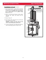
DISASSEMBLY OF BASE
(Figure 4)
1. Disconnect Top Guard (95) from Manifold Block (68)
by unfastening two Screws (96), and slide it over the
Hydraulic Hoses out of the way.
2. Disconnect Air Fitting (64) from Manifold Block.
3. Unscrew both Swivel Assemblies (20) from Manifold
Block.
4. Remove Lower Guard (97) from Cylinder Assy (53)
by unfastening two Screws (98).
5. Remove Retaining Ring (76) from top of Cylinder.
6. Remove End Cap (77) from Cylinder.
7. Remove Throttle Valve (36) from Cylinder.
8. Remove four Socket Head Screws (69) from
Manifold Block (68) at top of Handle (21), and
carefully
lift Manifold Block straight up from Handle.
9. Remove two Reservoir Plugs (75) from top of
Manifold Block.
10. Remove Pull Gland Assembly (90) and Return Gland
Assembly (22) from the separated Handle and
Manifold Block, and remove seals from glands.
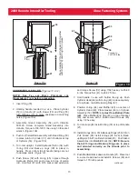
(Figure 5)
11. Hold remaining Handle and Cylinder Assembly
inverted in a vice and unscrew three Button Head
Screws (45) with 1/8 hex key.
12. Remove Muffler End Cap (42), Bottom Exhaust
Gasket (46), Muffler (43) and O-ring (44).
13. Remove Retaining Ring (47) from Cylinder Assembly
(53).
14. Screw Button Head Screws (45) into Cylinder Head
(49). Carefully pry under screws to remove Cylinder
Head.
15. Push Air Piston (51) all the way down in Cylinder. Lay
the tool on its side. Hold Nut (41) with a 9/16 socket
and extension, and with 7/64 hex key, remove piston
Screw (32). (Figure 6)
16. Turn Cylinder and Handle upside down again and
secure in a vise.
continued
36
76
22
68
20
64
63
69
90
21
53
77
97
98
75
96
95
Figure 4
21
54
53
52
50
51
48
49
47
44
43
46
42
45
41
Figure 5


