


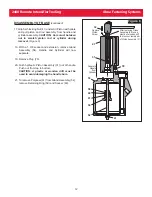


Fill Point
Fill Bottle
(94)
Plastic
Tube (93)
Connector
(92)
17
2480 Remote Intensifier Tooling Alcoa Fastening Systems
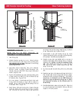
FILL AND BLEED PROCEDURE FOR
ASSEMBLED TOOLS THAT NEED RE-
BLEEDING
(Figure 12)
If the tool is not developing full stroke or is not
developing enough force to either install a fastener or
eject off an installed fastener, it may be necessary to add
oil to the pull and return system of the tool.
1. To add fluid to the PULL or RETURN side ports, first
make sure Cutoff Valves (70) are in the fully closed
position.
2. Remove Reservoir Plugs (75) and thread two
Reservoirs (66) with O-Rings (91) in place into the
ports of the Manifold Block (68).
3. Remove the Caps (65) and Piston Assys (67) from
the Reservoirs, and add fluid to the Reservoirs.
NOTE: Do not fill past the inside shoulder of the
Reservoirs (NO higher than Vent Hole). See Step
2 of figure 6
4. Replace Piston Assemblies and Caps on
Reservoirs.
5. Open the Cutoff Valves 1/4 turn counterclockwise.
Thread Piston Assemblies down to force fluid into
the system, and until Piston Assemblies cannot be
turned further.
6. Close Cutoff Valves tightly, and check tool stroke.
Repeat Steps 3 through 5 if necessary. If stroke is
correct, install a test fastener.
7. Remove the Reservoir Assemblies and replace the
two Reservoir Plugs (75) and tighten.
CAUTION:
Oil may be present in Reservoir tubes. Remove
with care.
R
P
RETURN
PULL
Step 1
Turn Threaded Rod of Piston Assy
counterclockwise until the Cap
unscrews out of the reservoir.
Step 2
Fill Reservoir with
hydraulic fluid to
top of piston bore
Relief
Valve (72)
Bleed Plug
Assembly (73)
Step 3
Thread Rod
down flush to
top of Cap.
Threaded
Rod
Cap (65)
Piston
Assy (67)
Reservoir
(66)
Manifold
Block (68)
Cutoff
Valves (70)
R
P
Step 4
Thread two
Reservoir Plugs
back into ports.
Vent Hole
Figure 12
WARNING: Avoid
contact with hydraulic
fluid. Hydraulic fluid
must be disposed of in
accordance with
Federal, State and
Local Regulations.
Please see MSDS for
Hydraulic fluid
shipped with tool.
!
Figure 11
F
ILL AND
B
LEED
P
ROCEDURE
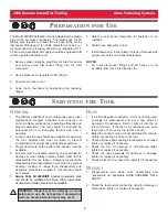
Equipment Required:
- Shop airline with 90 - 100 psi max.
- Air regulator
- Fill Bottle (94), Tube (93), and Connector (92)
(supplied with tool).
- Large flat blade screwdriver
- Nose assembly
- Fasteners (Optional)
Preparation:
1. Install air regulator in airline and set
pressure to 20-40 psi.
2. Fill bleed Bottle (94) almost full of DEXRON III
ATF or equivalent and secure Bottle cap.
(Figure 11)
3. Install Plastic Tube (93) and Connector (92) on
tip of Bottle Cap.
USE AUTOMATIC TRANSMISSION FLUID
DEXRON III, OR EQUIVALENT.
(Not to Scale)