16
2480 Remote Intensifier Tooling Alcoa Fastening Systems
ASSEMBLY OF BASE
(continued)
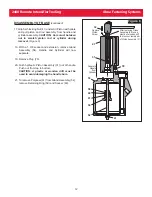
12. Install two Cutoff Valves (70) with O-Rings (71) in
place, Relief Valve (72) with O-Ring (71) in place,
and Bleed Plug Assembly (73).
13. Drop Spring (40) into Throttle valve hole in cylinder.
Push Throttle Valve (36) with O-rings (37 & 39) in
place into Cylinder.
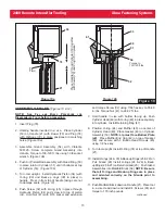
14. Carefully press Throttle Valve (79) with O-rings (37,
39 and 55) in place into Cylinder until seated.
15. Push End Cap (77) with O-ring (81) in place into
Cylinder and secure with Retaining Ring (76).
16. Attach Lower Guard (97) with two screws (98).
17. Slide Top Guard (95) over ends of Swivel
Assemblies (17) and Air Fitting (64), and screw
Swivel Assemblies and Air Fitting into Manifold Block
(68). Secure Top Guard in place with two Screws
(96).
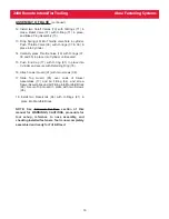
18. Install two Reservoirs (66) with O-Rings (91) in
place into Manifold Block.
NOTE: See S
ERVICING
T
HE
T
OOL
section of this
manual for WARNINGS, CAUTIONS, procedure for
tool set-up, reference to nose assembly, and
checking installed fasteners. Tool is now completely
assembled and ready for Fill & Bleed.


