13
2480 Remote Intensifier Tooling Alcoa Fastening Systems
A
SSEMBLY
GENERAL ASSEMBLY GUIDELINES
Clean all tool components with mineral spirits or
similar solvent. Inspect for wear/damage and replace
as necessary. Always replace all seals on/in
disassembled components. Use O-rings and back-up
rings supplied in SERVICE PARTS KIT 2480RIKIT.
Smear LUBRIPLATE 130AA or equivalent on O-rings,
back-up rings and mating components for ease of
assembly. Assemble Tool taking care not to damage
either O-rings or back-up rings.
ASSEMBLY OF HEAD
(Figures 7 & 8)
NOTE: Be sure that all seals are in place and oriented
correctly in the Cylinder (12) and on the Piston (4)
and Gland (10) prior to assembling.
1. Thinly coat SUPER 0-LUBE, or equivalent, on seals
and mating surfaces. Assemble O-rings and back-up
rings to piston, front gland, and rear gland. Press
Polyseal into front gland housing.
Caution: Be
carefull that Polyseal does not hang up on the
edge of the Piston chamfer. Seal will be damaged
and leakage may result.
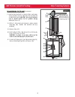
2. Thread Piston Assembly Tool onto Piston. Lubricate
Polyseal inside diameter and external diameters of
Piston and Piston Assembly Tool. Press evenly
against Gland Cap to slide Front Gland Assembly
over Piston Assembly Tool and into Piston. Slide
Wiper onto Piston as shown.
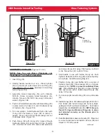
3. Thread Piston Insertion Tool into cylinder. Lightly coat
internal surfaces of tool and Cylinder with lubricant.
4. Lightly coat Cylinder, Piston O-Rings, and Front
Gland O-Rings with lubricant. While supporting tool,
as shown, press assembled Piston and components
into Cylinder.
(Figure 7)
Remove Piston Assembly
Tool.
5. Lightly coat Cylinder and Rear Gland
O-rings with lubricant. Hold Cylinder
upright on a bench or in a vice fitted
with soft jaws. Install Rear Gland
Assembly using suitable spacer, plate,
and soft mallet. Remove Piston
Insertion Tool.
6. Press Wiper into groove of End Cap.
Thread End Cap into Cylinder and
tighten. Install Pintail Deflector.
(Figure 8)
continued
Support
Press
Piston
5
6
7
8
9
10
8
11
14
9
8
15
13
Spacer
Piston
Assembly
Tool
Piston
Insertion
Tool
Note
Polyseal
Orientation
Front
Gland
Assy
Rear
Gland
Assy
Note
Poly
Orie
Figure 7
End
Cap
Wiper
Pintail
Deflector
W
Figure 8


