


D
ISASSEMBLY
9
2480 Remote Intensifier Tooling Alcoa Fastening Systems
NOTE: The following procedure is for complete
disassembly of tool. Disassemble only components
necessary to replace damaged O-rings, Quad rings,
Back-up rings, and worn or damaged components.
Always use soft jaw vice to avoid damage to tool.
DISASSEMBLY OF HEAD
For list of Item Numbers and their locations, refer to
complete Tool Assembly Drawing and Parts List.
I.
See
WARNING
above. Disconnect tool’s electrical
connector from hydraulic unit. Uncouple tool’s
hydraulic hoses.
2.
Remove nose assembly from tool.
3.
Remove four Socket Head Cap Screws (99) and
Locknuts (100) from handle assembly. Separate
Handle (19) halves.
(Figure 1)
4.
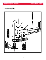
Lift Air Trigger Assembly (1) from Handle half. Pull Air
Hose out of handle’s built-in strain relief.
(Figure 1)
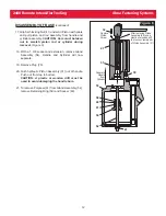
5.
Unscrew Hydraulic Hoses (63) from tool.
(Figure 9)
Drain hoses into container. Piston (4) can be pushed
to rear of Cylinder (12) to drain fluid. Discard fluid.
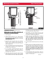
6. Disassemble cylinder and piston assembly as follows:
a.) Place Spacer over threaded end of Piston
(Figure
2a)
. Thread Piston Assembly Tool onto Piston. If
Cylinder contains fluid, push Piston to rear and
drain into container. Discard fluid.
b.) Remove Pintail Deflector (18) from tool by twisting
and pulling in one motion. With a 1 5/16 open end
wrench, unscrew End Cap (17).
c.) Thread Piston Insertion Tool into back of Cylinder.
(Figure 2b)
d.) Supporting tool as shown, press (or drive) Piston,
Rear Gland (13) assembly and Front Gland (10)
assembly out of Cylinder.
(Figure 2c)
continued
WARNING: Be sure to disconnect Tool’s
control trigger system from POWERIG®
Hydraulic Unit before disconnecting Tool’s
hydraulic hoses from unit. If not disconnected
in this order before any maintenance or
cleaning is done, severe personal injury may
occur.
!
Left half of
Handle (19)
Right half of
Handle (19)
Locknut
(100)
Qty. 4
Hydraulic Hoses
(63)
Qty. 2
Head Assembly
Air Trigger
and Hose
Assembly (1)
Socket Head
Cap Screw (99)
Qty. 4
Figure 1


