1
15
FS1 Installation and Operation Manual — Connectors
•
SDI In/Out
—digital video with embedded audio. There are two input and two
output BNC connectors. The outputs are active all the time, although you must
specify the output format (and thus whether any conversion takes place). SDI 2
can follow the input (“bypass”)—see description on the following page.
•
Component In/Out YPbPr/RGB
—video, 3 BNCs for input, and 3 BNCs for output.
Component can follow the input (“bypass”)—see the description on the following
page.
•
S-Video In/Out
(Y/C)—one 4-pinmini-DIN for input, and one 4-pin mini-DIN for
output—see the description on the following page.
•
Composite In/Out
—NTSC/ PAL video, 1 BNC for input, and 1 BNC for output—see
the description on the following page.
•
Ref Loop
—reference video (looping), 2 BNCs.
•
RS-422
—DE-9 connector reserved for future use.
Each of these groups of connectors are discussed on the following pages.
Connector
Descriptions
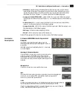
8 Channel AES/EBU Audio Inputs And
Outputs
One BNC is provided for each of four pairs of
channels, both on the input and output: 1/2, 3/4, 5/
6, and 7/8.
AES/EBU signals are handled by the FS1 internally
as 24-bit digital.
Analog 8 Channel Audio
The two DB25 connectors, one for input and one for
output, support a TASCAM-style cable snake for
balanced 8-channel audio. Analog audio signals are
converted internally to 24-bit digital audio inputs and
outputs.
RS-422 Port
This DE-9 connector is reserved for future use.
GPI
A female DE-9 connector provides connection to external equipment
or circuits via an isolated TTL-compatible interface.
Appendix B
contains a pinout and specifications.
LAN
An RJ45 connector provides a 10/100 Ethernet port for connection directly
to a computer or Ethernet hub or switch for connecting to a LAN.
The FS1is compatible with CAT-5 straight-through or cross-over Ethernet
cables, automatically detecting which is used.

