14
Rear Panel
About Inputs and
Outputs
The functions of the FS1
Inputs and Outputs depend on the operational mode.
The operational steps are simple:
1.
Select an output format.
2.
Select the desired input.
All outputs are active all the time. If you select an output format first and then the
input source, the FS1 automatically performs up/down/cross conversion.
Audio embedding/disembedding is also automatic, according to the parameter
settings you’ve selected. For example, even though the input selected might be HD-
SDI with embedded audio, the analog audio output connectors will output proper
analog audio that has been disembedded from the serial digital stream.
Please study
Chapter 4 Parameter Menus
, for a full understanding of all the possible
FS1 settings.
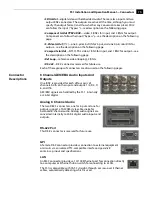
Connectors
Connectors on the rear panel are arranged in groups for easy installation and
maintenance:
•
P/S 1
and
P/S 2
—AC power
connectors, each 3-pin (with Ground), one for each
independent power supply. Each power supply is autosensing from 100 to
240VAC at 50/60Hz. Only one has to be connected for FS1 operation, but
redundant operation is available only if both connectors are plugged into AC
power.
•
AES/EBU Audio
—8 digital channels in and out, two pairs per BNC.
•
Analog Audio Ch.1-8 In/Out
—8 channels of analog audio in and out via a DB25
TASCAM-style cable (not supplied).
•
GPI
—
connector providing dual isolated TTL compatible inputs and outputs. The
functions of each are selectable in software.
•
10/100 LAN
—
RJ45 Ethernet connector.
Serial
Digital
In/Out
(SD-SDI
HD-SDI)
S-Video
In/Out
Composite
In/Out
10/100
RJ45
Ethernet
LAN
Connector
GPI
9-pin
Connector
ID (Identify)
LED
RS422
DB9 Connector
(Reserved for Future Use)
External
Reference
with Loop-
Through
AC Power Supply
Socket #2
Autosensing
100 to 240VAC, 0.3A
50/60Hz
AC Power Supply
Socket #1
Autosensing
100 to 240VAC, 0.3A
50/60Hz
Component
YPbPr and
RGB In/Out
Analog Audio In/Out
Channels 1 through 8
(uses Tascam-style
cable)
AES/EBU Digital
Audio In/Out
Channels 1 through 8


