2
Gen IV Controller with Smart Arm Setup Instruction Manual
1. Introduction . . . . . . . . . . . 2
2 Equipment/Software. . . . . . . . . 2
3. Hardware Setup . . . . . . . . . . 2
4. Hardware Connection . . . . . . . . 3
5. Care Setup Steps Overview . . . . . . 3
6. Functionality Overview . . . . . . . . 3
7. Configuration of the Smart Arm Accessory . 4
7.1 Configuration Overview . . . . . . . 4
7.2 Accessory Setup Screen . . . . . . 4
7.3 Accessory Scanning and IP Setup Screen 5
7.4 Main Configuration Screen. . . . . . 5
7.5 Encoder Position Setup . . . . . . . 6
7.5.1 Homing . . . . . . . . . . 6
7.5.2 Encoder Location Setup Screen . 6
8. Smart Arm Runscreen . . . . . . . . 7
8.1 Add, Edit, or Delete Custom Images . . 7
8.2 Associate an Image with a Job . . . . 8
9. Examples . . . . . . . . . . . . 9
9.1 Example 1: Select PSets Based on Location 9
9.1.1 PSet Setup . . . . . . . . . 9
9.1.2 Accessory Setup . . . . . . . 10
9.1.3 Add Image for Runscreen . . . 10
9.1.4 Icon Reference . . . . . . . 11
9.1.5 Clearing locations . . . . . . 11
9.2 Example 2: Command Bolt Locations via
External Source . . . . . . . . . 11
9.2.1 PSet Setup . . . . . . . . . 12
9.2.2 Job Setup . . . . . . . . . 12
9.2.3 Accessory Setup . . . . . . . 12
9.2.4 External Control . . . . . . . 13
9.2.5 Add Image for Runscreen . . . 13
9.2.6 Clearing locations . . . . . . 14
10. Adding a Proximity or Limit Switch . . . . 14
11. Icon Reference . . . . . . . . . . 14
12. References . . . . . . . . . . . . 14
Table of Contents
1. Introduction
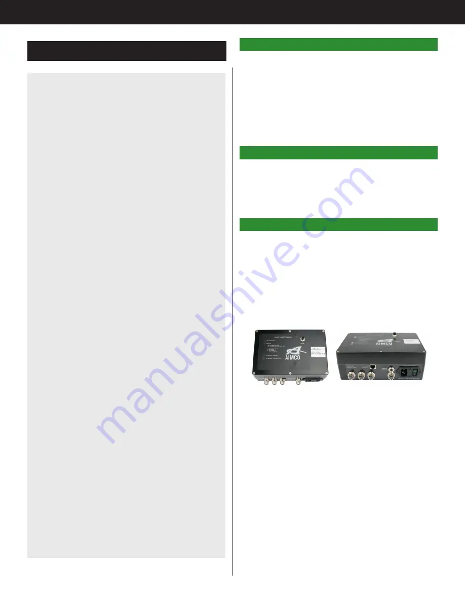
The Smart Arm Accessory allows an articulated arm
with encoders to be used with the Gen IV controller.
Fastener locations can be programmed into the
controller so that the controller will perform specific
actions when the tool is located on a specific
fastener. The controller can also be configured to
show a custom image on the Runscreen with fastener
locations that update as fastenings are performed.
2 Equipment/Software
• AIMCO Gen 4 controller.
• Power Supply Cable.
• Smart Arm Accessory – Encoder Interface - 30860
• Ethernet Cable
3. Hardware Setup
• Connect power to the Gen IV controller
• Connect power to the Smart Arm Accessory
• Connect an Ethernet cable from the Accessory
box to the second Ethernet port on the Gen IV
Controller.
• Connect the encoders from the arm to the
accessory box via M12 cables.
• Power up the Smart Arm Accessory
• Power up the Gen IV Controller
Summary of Contents for AcraDyne
Page 15: ......


