7
Gen IV Controller with Smart Arm Setup Instruction Manual
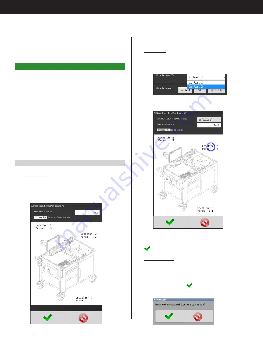
Enter a unique identifier as the Part Image Name
and click "Choose File" to navigate to and select
the custom image file. Image will appear on the
screen.
•
Edit Image
From the Main Configuration Screen, select the
"Part Image ID" of the part you want to edit, then
click "Edit."
The Editing screen will appear
Edit as necessary (for instructions, see "8.1.3 Add
Image for Runscreen" on page 10), then click
to return to the Main Configuration Screen.
•
Delete Image
From the Main Configuration Screen, select the
"Part Image ID" of the part you want to edit, then
click "Delete." Deleting an image is permanent
and doing so will delete all encoder positions/
location data. Click
to permanently delete
the image.
•
Use Current Position:
Selecting this option will
grab the current state of the encoders and use it
as the target. Use this to easily add a location by
positioning the tool on the bolt and clicking ‘Use
Current Position.’ Click OK at the bottom of the
screen and this location will be added to the list.
8. Smart Arm Runscreen
Uploading a custom image allows you to visualize
the fastening locations of your project on the Smart
Arm Runscreen. This feature was added in SYSREL
3R18 (Application version 1.95)
The basic steps to set up the runscreen are:
1. Perform all steps previously shown to connect to
the smart arm, add all fastener locations, and
determine whether the arm position changes
pset/job sequence/etc.
2. Upload an image that will show the locations of
fasteners. Image must be 470 x 550 pixels for best
fit to controller screen
3. Associate the fastener locations to locations on
the image
8.1 Add, Edit, or Delete Custom Images
•
Add Image
Click 'Add' to upload a custom image for the
runscreen. This opens the part image upload
page. Images must be 470 x 550 pixels for best fit
to controller screen.
Summary of Contents for AcraDyne
Page 15: ......


