


Performance Tests
3
Installation and Verification Manual
75
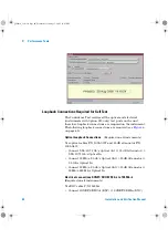
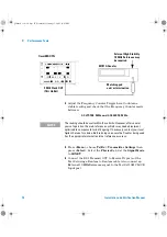
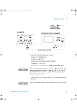
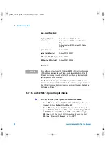
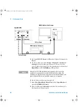
Equipment Required
(External 2M Clock as Reference)
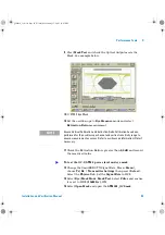
1
Press
<Menu>
, choose
Tx/Rx > Stored Settings
then press
<Select>
. Select
Default
the
Recall
.
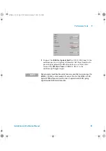
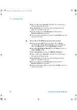
2
Press
<Menu>
, choose
Tx/Rx > Transmitter Settings
then
press
<Select>
. Select the
Physical
tab. Set the
Signal Mode
to
SDH.
Now set
Clock Source
to
External
,
Format
to
2Mb/s Clock
.
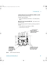
3
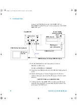
Connect the OmniBER OTN’s 2 MHz Clock Out port to the
Frequency Counter Input using a 75/50
Ω
matching pad, set
the input impedance to 50
Ω
. Alternatively, a 75
Ω
termination
can be used with the input impedance set to 1M
Ω
.
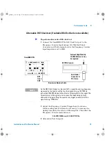
Connect the Counter rear panel 10 MHz Reference Output to
the PDH/DSn Test Set external 10M CLOCK input port.
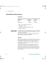
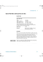
Frequency Counter
Agilent 53181A Option 010,015 (see Note)
DSn Test Set
Agilent 37718C with Option 012
Bantam/Bantam Cables (2)
Agilent 15670A
75/50 ohm Matching Pad
Agilent E2629A
Bal/Unbal Converter
Agilent 15508B
N O T E
For accuracy required the counter MUST have high stability Internal Timebase
option or be externally referenced to an in-house Standard.
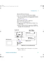
To test the external clock reference inputs and output
panther3_iv.book Page 75 Wednesday, January 15, 2003 12:03 PM