


36
Installation and Verification Manual
2
Installation (Getting Started)
Connecting to the Power Supply
As the IEC320 coupler is the disconnect device, consideration
must be given to the following when installing the instrument in
a rack:
•
An adequately rated switch (250V, 10A) or circuit breaker
(250V, 5A) shall be included in the rack.
•
It should be in close proximity to the instrument and within
easy reach of the operator.
•
It shall be marked as a disconnect device.
WA R N I N G
This is a Safety Class I instrument (provided with a protective
earthing ground, incorporated in the power cord). The mains plug
shall only be inserted in a socket outlet provided with a protective
earth contact. Any interruption of the protective conductor inside or
outside of the instrument is likely to make the instrument dangerous.
Intentional interruption is prohibited.
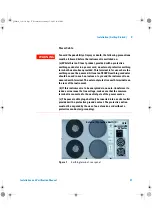
The mains switch fitted to the instrument is a single pole device and
must not be used as the disconnect device. An IEC320 coupler is
intended as the main disconnect device. The switch is marked I and
0. The I indicates on and the O indicates off. Do not position the
instrument such that access to the coupler is impaired.
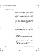
Before switching on this instrument, make sure that the line supply
voltage is in the specified ranges. Range selection is automatic.
panther3_iv.book Page 36 Wednesday, January 15, 2003 12:03 PM