


Getting Started
2
Installation and Verification Manual
51
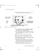
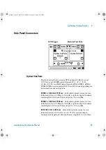
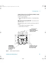
DS1 Clock In
Bantam 100 ohm (nominal) connector for a DS1
BITS external reference clock input.
2 Mb/s, 2 MHz, 10 MHz Clock In
BNC 75 ohm (nominal)
unbalanced connector for a 2 Mb/s and 2 MHz MTS external
clock source input. You can also use this connector to input a 10
MHz clock reference.
2 Mb/s, 2 MHz Clock In
3-pin Siemens connector for a 2 Mb/s
and 2 MHz MTS external clock source input.
TX Eye Clock 52 - 2.66 Mb/s
SMA connector providing a TX Eye
Clock signal (at 1/4 of the line rate) which can be used to trigger
an oscilloscope when examining data signals.
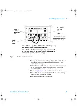
2 MHz Clock Out
BNC 75 ohm (nominal) unbalanced connector
for a 2 MHz MTS clock reference output. Generated relative to
the selected transmit reference clock.
DS1 Clock Out
Bantam 100 ohm (nominal) connector for a DS1
BITS clock reference output. Generated relative to the selected
transmit reference clock.
DCC/GCC Port/Trigger Port
Connector
9-pin miniature D-type.
Use this port to drop and insert OTN GCC channels (OTU GCC0,
ODU GCC1, ODU GCC2), the D1-D3 DCC channel or the D4-D12
DCC channel. This port is also used to output transmitter and
receiver triggers. The first bit of data inserted will be put into
the MSB of the DCC channel. The MSB of the dropped data
bytes will be output first. The drop and insert capabilities are
independent, that is the transmit and receive clock rates can be
set to different rates. Note that the instrument acts as a DCE
(Data Communications Equipment), supplying the clock signal
for both drop and insert operation.
panther3_iv.book Page 51 Wednesday, January 15, 2003 12:03 PM