

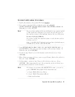


7.
When
the
analyzer
nishes
the
sweeps
,
record
the
data
trace
mean
value
(as
shown
on
the
upper
right-hand
corner
of
the
analyzer
display)
on
the
\P
erformance
T
est
Record
(14
of
28)."
8.
Press
4
MENU
5
NNNNNNNNNNNNNNNNN
POWER
NNNNNNNNNNNNNNNNNNNNNNNNNNNNNNNNNNNNNN
POWER
RANGES
NNNNNNNNNNNNNNNNNNNNNNNNNNNNNNNNNNNNNNNNNNNNNNNNNNN
RANGE
1
025
to
0
.
Enter
the
power
level
value
listed
in
the
\P
erformance
T
est
Record."
F
or
this
power
range
,
press
4
0
5
4
2
5
4
0
5
4
x1
5 .
9.
Repeat
steps
6,
7
and
8
for
the
other
power
ranges
listed
in
the
\P
erformance
T
est
Record
(14
of
28)."
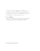
P
ower
Level
Linearity
for
an
HP
8752C
with
Option
004
or
an
HP
8752C
with Options
004
and
075
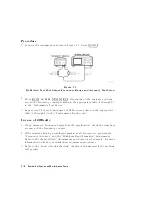
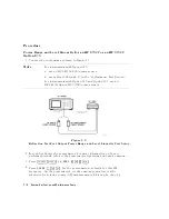
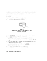
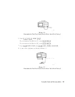
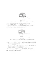
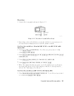
1.
Connect
the
equipment
as
shown
in
Figure
2-5.
Note
F
or
instruments
with
Option
075:
a.
use
an
HP
8483A
(75)
power
sensor
b.
use
tables
19
through
21
in
the
\P
erformance
T
est
Record."
F
or
instruments
with
Option
075
and
Option
003,
use
an
HP
8483A
Option
H03
(75)
power
sensor
.
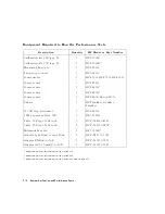
Figure
2-5.
Reection
T
est
P
ort
Output
P
ower
Level
Linearity
T
est
Setup
System
V
erication
and
P
erformance
T
ests
2-21
Summary of Contents for 8752C
Page 22: ...Before Applying Power 15 6 Servicing 15 6 Index Contents 16 ...
Page 38: ......
Page 43: ...Figure 2 1 Measurement Uncertainty Window System Veri cation and Performance Tests 2 5 ...
Page 116: ......
Page 122: ...Figure 3 1 Location of Major Assemblies 3 6 Adjustments and Correction Constants ...
Page 176: ......
Page 192: ...4 16 Start Troubleshooting Here ...
Page 193: ......
Page 195: ...Figure 4 7 HP 8752C Overall Block Diagram 3 of 4 Option 006 4 20 Start Troubleshooting Here ...
Page 197: ......
Page 221: ...5 24 Power Supply Troubleshooting ...
Page 222: ......
Page 271: ...Figure 7 21 A14 Generated Digital Control Signals Source Troubleshooting 7 31 ...
Page 302: ......
Page 366: ......
Page 378: ...Figure 11 4 Typical ED Re ection Test Port 11 12 Error Terms ...
Page 380: ...Figure 11 5 Typical ES Re ection Test Port 11 14 Error Terms ...
Page 382: ...Figure 11 6 Typical ER Re ection Test Port 11 16 Error Terms ...
Page 386: ...Figure 11 9 Typical ET 11 20 Error Terms ...
Page 407: ...Figure 12 5 High Band Operation of the Source Theory of Operation 12 21 ...
Page 410: ...Figure 12 6 Receiver Functional Group standard and Option 003 12 24 Theory of Operation ...
Page 411: ...Figure 12 7 Receiver Functional Group Option 003 and 004 Theory of Operation 12 25 ...
Page 412: ...Figure 12 8 Receiver Functional Group Option 006 12 26 Theory of Operation ...
Page 413: ...Figure 12 9 Receiver Functional Group Option 004 and 006 Theory of Operation 12 27 ...
Page 416: ......
Page 419: ...Figure 13 1 Module Exchange Procedure Replaceable Parts 13 3 ...
Page 423: ...Major Assemblies Replaceable Parts 13 7 ...
Page 425: ...Front Panel Assemblies Replaceable Parts 13 9 ...
Page 427: ...Rear Panel Assemblies Replaceable Parts 13 11 ...
Page 429: ...Cables Top View Replaceable Parts 13 13 ...
Page 431: ...Front Panel Cables and Attaching Hardware Replaceable Parts 13 15 ...
Page 433: ...Rear Panel Cables and Attaching Hardware Replaceable Parts 13 17 ...
Page 435: ...Source and Sampler Parts Standard and Option 003 Replaceable Parts 13 19 ...
Page 437: ...Source and Sampler Parts Option 004 006 Replaceable Parts 13 21 ...
Page 439: ...Source and Sampler Parts Options 004 and 003 004 Replaceable Parts 13 23 ...
Page 441: ...Source and Sampler Parts Option 006 Replaceable Parts 13 25 ...
Page 443: ...Display Bezel Assembly Replaceable Parts 13 27 ...
Page 445: ...Chassis Parts Replaceable Parts 13 29 ...
Page 447: ...Top View of Attaching Hardware and Post Regulator Fuses Replaceable Parts 13 31 ...
Page 449: ...Bottom View of Attaching Hardware Replaceable Parts 13 33 ...
Page 488: ......