


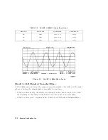


Phase
Lock
Diagnostic
Routines
P
erform
the
following
steps
to
determine
at
what
frequencies
and
bands
the
phase
lock
problem
occurs
.
1.
Press
4
PRESET
5
4
SYSTEM
5
N
NNNNNNNNNNNNNNNNNNNNNNNNNNNNNNNNNNNNN
SERVICE
MENU
NNNNNNNNNNNNNNNNNNNNNNNNNNNNNNNNNNNNNNNNN
SERVICE
MODES
NNNNNNNNNNNNNNNNNNNNNNNNNNNNNNNNNNNNNN
PLL
AUTO
OFF
to
switch
o
the
automatic
phase-locked
loop
.
Normally
,
when
the
phase-locked
loop
detects
lock
problems
,
it
automatically
aborts
the
sweep
and
attempts
to
recalibrate
the
pretune
cycle
.
Switching
o
PLL
A
UTO
defeats
this
routine
.
2.
Press
NNNNNNNNNNNNNNNNNNNNNNNNNNNNNNNNNNN
PLL
DIAG
ON
to
switch
on
the
phase-locked
loop
diagnostic
service
mode
.
In
this
mode
,
the
phase
lock
cycle
and
subsweep
number
are
displayed
on
the
analyzer
display
.
(See
\Service
modes
menu"
in
the
\Service
Key
Menus
and
Error
Messages"
chapter
for
more
information.)
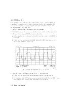
3.
Press
N
NNNNNNNNNNNNNNNNNNNNNNNNNNNN
PLL
PAUSE
to
pause
the
phase
lock
sequence
and
determine
where
the
source
is
trying
to
tune
when
lock
is
lost.
Refer
to
\Source
theory"
in
the
\Theory
of
Operation"
chapter
for
additional
information
regarding
band
related
problems
.
Then
use
the
procedures
in
this
chapter
to
check
source
functions
at
specic
frequencies
.
Broadband
P
ower
Problems
This
section
assumes
that
a
power
problem
exists
across
the
full
frequency
range
,
but
that
no
error
message
is
displayed
on
the
analyzer
.
The
problem
will
only
eect
the
reection
test
port.
Assemblies
in
question
include:
A3
source
A30
dual
directional
coupler
any
cables
from
the
A3
source
to
the
output
of
the
reection
test
port
7-40
Source
T
roubleshooting
Summary of Contents for 8752C
Page 22: ...Before Applying Power 15 6 Servicing 15 6 Index Contents 16 ...
Page 38: ......
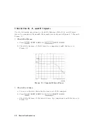
Page 43: ...Figure 2 1 Measurement Uncertainty Window System Veri cation and Performance Tests 2 5 ...
Page 116: ......
Page 122: ...Figure 3 1 Location of Major Assemblies 3 6 Adjustments and Correction Constants ...
Page 176: ......
Page 192: ...4 16 Start Troubleshooting Here ...
Page 193: ......
Page 195: ...Figure 4 7 HP 8752C Overall Block Diagram 3 of 4 Option 006 4 20 Start Troubleshooting Here ...
Page 197: ......
Page 221: ...5 24 Power Supply Troubleshooting ...
Page 222: ......
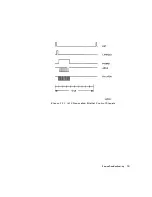
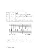
Page 271: ...Figure 7 21 A14 Generated Digital Control Signals Source Troubleshooting 7 31 ...
Page 302: ......
Page 366: ......
Page 378: ...Figure 11 4 Typical ED Re ection Test Port 11 12 Error Terms ...
Page 380: ...Figure 11 5 Typical ES Re ection Test Port 11 14 Error Terms ...
Page 382: ...Figure 11 6 Typical ER Re ection Test Port 11 16 Error Terms ...
Page 386: ...Figure 11 9 Typical ET 11 20 Error Terms ...
Page 407: ...Figure 12 5 High Band Operation of the Source Theory of Operation 12 21 ...
Page 410: ...Figure 12 6 Receiver Functional Group standard and Option 003 12 24 Theory of Operation ...
Page 411: ...Figure 12 7 Receiver Functional Group Option 003 and 004 Theory of Operation 12 25 ...
Page 412: ...Figure 12 8 Receiver Functional Group Option 006 12 26 Theory of Operation ...
Page 413: ...Figure 12 9 Receiver Functional Group Option 004 and 006 Theory of Operation 12 27 ...
Page 416: ......
Page 419: ...Figure 13 1 Module Exchange Procedure Replaceable Parts 13 3 ...
Page 423: ...Major Assemblies Replaceable Parts 13 7 ...
Page 425: ...Front Panel Assemblies Replaceable Parts 13 9 ...
Page 427: ...Rear Panel Assemblies Replaceable Parts 13 11 ...
Page 429: ...Cables Top View Replaceable Parts 13 13 ...
Page 431: ...Front Panel Cables and Attaching Hardware Replaceable Parts 13 15 ...
Page 433: ...Rear Panel Cables and Attaching Hardware Replaceable Parts 13 17 ...
Page 435: ...Source and Sampler Parts Standard and Option 003 Replaceable Parts 13 19 ...
Page 437: ...Source and Sampler Parts Option 004 006 Replaceable Parts 13 21 ...
Page 439: ...Source and Sampler Parts Options 004 and 003 004 Replaceable Parts 13 23 ...
Page 441: ...Source and Sampler Parts Option 006 Replaceable Parts 13 25 ...
Page 443: ...Display Bezel Assembly Replaceable Parts 13 27 ...
Page 445: ...Chassis Parts Replaceable Parts 13 29 ...
Page 447: ...Top View of Attaching Hardware and Post Regulator Fuses Replaceable Parts 13 31 ...
Page 449: ...Bottom View of Attaching Hardware Replaceable Parts 13 33 ...
Page 488: ......