


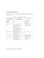


T
able
14-1.
P
ost-Repair
Procedures
(continued)
Replaced
or
Repaired
Assembly
A
djustments
Correction
Constants
(CC)
V
erication
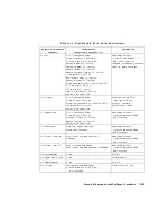
A9
CPU
A9
CC
Jumper
P
osition
Model
Number
CC
(75
only)
Display
Intensity
CC
(T
est
49)
Serial
Number
CC
(T
est
55)
Option
Number
CC
(T
est
56)
Source
Default
CC
(T
est
44)
Source
Pretune
Default
CC
(T
est
45)
Analog
Bus
CC
(T
est
46)
RF
Output
P
ower
CC
(T
est
47)
Source
Pretune
CC
(T
est
48)
Frequency
response
CC
(T
ests
53
and
57)
ADC
Oset
CC
(T
est
52)
IF
Amplier
CC
(T
est
51)
Cavity
Oscillator
CC
(T
est
54)
EEPROM
Backup
Disk
Reection
T
est
P
ort
Output
P
ower
Range
and
Level
Linearity
Magnitude
Dynamic
A
ccuracy
Phase
Dynamic
A
ccuracy
A10
Digital
IF
A9
CC
Jumper
P
osition
Analog
Bus
CC
(T
est
46)
Frequency
Response
CC
(T
ests
53
and
57)
IF
Amplier
CC
(T
est
51)
EEPROM
Backup
Disk
Transmission
T
est
P
ort
Input
Noise
Floor
T
est
P
ort
Crosstalk
System
Trace
Noise
A11
Phase
Lock
A9
CC
Jumper
P
osition
Analog
Bus
CC
(T
est
46)
Pretune
Default
CC
(T
est
45)
Source
Pretune
CC
(T
est
45)
EEPROM
Backup
Disk
Reection
T
est
P
ort
Output
Frequency
Range
and
A
ccuracy
A12
Reference
High/Low
Band
Transition
Frequency
A
ccuracy
Reection
T
est
P
ort
Output
Frequency
Range
and
A
ccuracy
A13
Frac-N
(Analog)
Frac-N
Spur
A
voidance
and
FM
Sideband
Reection
T
est
P
ort
Output
Frequency
Range
and
A
ccuracy
A14
Frac-N
(Digital)
Frac-N
Frequency
Range
Frac-N
Spur
A
voidance
and
FM
Sideband
Reection
T
est
P
ort
Output
Frequency
Range
and
A
ccuracy
A15
Preregulator
None
Self
T
est
A16
Rear
P
anel
Board
None
Internal
T
est
13
A17
Motherboard
None
Self
T
est
A18
Display
V
ertical
P
osition
and
F
ocus
Display
Intensity
CC
(T
est
49)
only
if
needed
Internal
T
ests
66
-
80
Assembly
Replacement
and
P
ost-Repair
Procedures
14-23
Summary of Contents for 8752C
Page 22: ...Before Applying Power 15 6 Servicing 15 6 Index Contents 16 ...
Page 38: ......
Page 43: ...Figure 2 1 Measurement Uncertainty Window System Veri cation and Performance Tests 2 5 ...
Page 116: ......
Page 122: ...Figure 3 1 Location of Major Assemblies 3 6 Adjustments and Correction Constants ...
Page 176: ......
Page 192: ...4 16 Start Troubleshooting Here ...
Page 193: ......
Page 195: ...Figure 4 7 HP 8752C Overall Block Diagram 3 of 4 Option 006 4 20 Start Troubleshooting Here ...
Page 197: ......
Page 221: ...5 24 Power Supply Troubleshooting ...
Page 222: ......
Page 271: ...Figure 7 21 A14 Generated Digital Control Signals Source Troubleshooting 7 31 ...
Page 302: ......
Page 366: ......
Page 378: ...Figure 11 4 Typical ED Re ection Test Port 11 12 Error Terms ...
Page 380: ...Figure 11 5 Typical ES Re ection Test Port 11 14 Error Terms ...
Page 382: ...Figure 11 6 Typical ER Re ection Test Port 11 16 Error Terms ...
Page 386: ...Figure 11 9 Typical ET 11 20 Error Terms ...
Page 407: ...Figure 12 5 High Band Operation of the Source Theory of Operation 12 21 ...
Page 410: ...Figure 12 6 Receiver Functional Group standard and Option 003 12 24 Theory of Operation ...
Page 411: ...Figure 12 7 Receiver Functional Group Option 003 and 004 Theory of Operation 12 25 ...
Page 412: ...Figure 12 8 Receiver Functional Group Option 006 12 26 Theory of Operation ...
Page 413: ...Figure 12 9 Receiver Functional Group Option 004 and 006 Theory of Operation 12 27 ...
Page 416: ......
Page 419: ...Figure 13 1 Module Exchange Procedure Replaceable Parts 13 3 ...
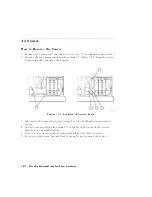
Page 423: ...Major Assemblies Replaceable Parts 13 7 ...
Page 425: ...Front Panel Assemblies Replaceable Parts 13 9 ...
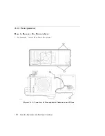
Page 427: ...Rear Panel Assemblies Replaceable Parts 13 11 ...
Page 429: ...Cables Top View Replaceable Parts 13 13 ...
Page 431: ...Front Panel Cables and Attaching Hardware Replaceable Parts 13 15 ...
Page 433: ...Rear Panel Cables and Attaching Hardware Replaceable Parts 13 17 ...
Page 435: ...Source and Sampler Parts Standard and Option 003 Replaceable Parts 13 19 ...
Page 437: ...Source and Sampler Parts Option 004 006 Replaceable Parts 13 21 ...
Page 439: ...Source and Sampler Parts Options 004 and 003 004 Replaceable Parts 13 23 ...
Page 441: ...Source and Sampler Parts Option 006 Replaceable Parts 13 25 ...
Page 443: ...Display Bezel Assembly Replaceable Parts 13 27 ...
Page 445: ...Chassis Parts Replaceable Parts 13 29 ...
Page 447: ...Top View of Attaching Hardware and Post Regulator Fuses Replaceable Parts 13 31 ...
Page 449: ...Bottom View of Attaching Hardware Replaceable Parts 13 33 ...
Page 488: ......