


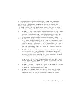

NNNNNNNNNNNNNNNNNNNNNNNNNNNNNNNNNNNNNNNNN
SYS
VER
TESTS
veries
the
analyzer
system
operation
by
examining
the
contents
of
the
measurement
calibration
arrays
.
The
procedure
is
in
the
\System
V
erication
and
P
erformance
T
ests"
chapter
.
Information
about
the
calibration
arrays
is
provided
in
the
\Error
T
erms"
chapter
.
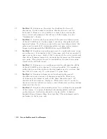
NNNNNNNNNNNNNNNNNNNNNNNNNNNNNNNNNNNNNNNNNNNNNNNNNN
ADJUSTMENT
TESTS
generates
and
stores
the
correction
constants
.
F
or
more
information,
refer
to
the
\A
djustments"
chapter
.
NNNNNNNNNNNNNNNNNNNNNNNNNNNNNNNNNNNNNNNNN
DISPLAY
TESTS
checks
for
correct
operation
of
the
display
and
GSP
board.
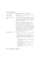
T
est
Options
Menu
T
o
access
this
menu,
press
4
SYSTEM
5
NNNNNNNNNNNNNNNNNNNNNNNNNNNNNNNNNNNNNN
SERVICE
MENU
NNNNNNNNNNNNNNNNNNNNNNNNNNNNNNNNNNNNNN
TEST
OPTIONS
.
NNNNNNNNNNNNNNNNNNNNNNNNNNNNNNNNNNNNNN
TEST
OPTIONS
accesses
softkeys
that
aect
the
way
tests
(routines)
run,
or
supply
necessary
additional
data.
NNNNNNNNNNNNNNNNNNNNNNNNNNNNNNNNNNNNNNNNN
CONTINUE
TEST
(TESR1)
resumes
the
test
from
where
it
was
stopped.
NNNNNNNNNNNNNNNNNNNNNNNNNNNNNNNNNNNNNNNNN
REPEAT
on
OFF
(TO2)
toggles
the
repeat
function
on
and
o.
When
the
function
is
ON,
the
selected
test
will
run
10,000
times
unless
you
press
any
key
to
stop
it.
The
analyzer
shows
the
current
number
of
passes
and
fails
.
NNNNNNNNNNNNNNNNNNNNNNNNNNNNNNNNNNNNNNNNN
RECORD
on
OFF
(TO1)
toggles
the
record
function
on
and
o.
When
the
function
is
ON,
certain
test
results
are
sent
to
a
printer
via
HP-IB
.
This
is
especially
useful
for
correction
constants
.
The
instrument
must
be
in
system
controller
mode
or
pass
control
mode
to
(refer
to
the
\Printing,
Plotting,
and
Saving
Measurement
Results"
chapter
in
the
HP
8752C
User's
Guide.
NNNNNNNNNNNNNNNNNNNNNNNNNNNNNNNNNNNNNNNNNNNNNNNNNNNNN
LIMITS[NORM/SPCL]
selects
either
NORMal
or
SP
eCiaL
(tighter)
limits
for
the
Operator's
Check.
The
SPCL
limits
are
useful
for
a
guard
band.
NNNNNNNNNNNNNNNNNNNNNNNNNNNNNNNN
POWER
LOSS
(POWLLIST)
accesses
the
following
Edit
List
menu
to
allow
modication
of
the
external
power
loss
data
table
.
Service
K
ey
Menus
and
Error
Messages
10-5
Summary of Contents for 8752C
Page 22: ...Before Applying Power 15 6 Servicing 15 6 Index Contents 16 ...
Page 38: ......
Page 43: ...Figure 2 1 Measurement Uncertainty Window System Veri cation and Performance Tests 2 5 ...
Page 116: ......
Page 122: ...Figure 3 1 Location of Major Assemblies 3 6 Adjustments and Correction Constants ...
Page 176: ......
Page 192: ...4 16 Start Troubleshooting Here ...
Page 193: ......
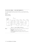
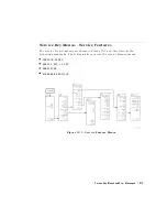
Page 195: ...Figure 4 7 HP 8752C Overall Block Diagram 3 of 4 Option 006 4 20 Start Troubleshooting Here ...
Page 197: ......
Page 221: ...5 24 Power Supply Troubleshooting ...
Page 222: ......
Page 271: ...Figure 7 21 A14 Generated Digital Control Signals Source Troubleshooting 7 31 ...
Page 302: ......
Page 366: ......
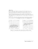
Page 378: ...Figure 11 4 Typical ED Re ection Test Port 11 12 Error Terms ...
Page 380: ...Figure 11 5 Typical ES Re ection Test Port 11 14 Error Terms ...
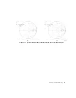
Page 382: ...Figure 11 6 Typical ER Re ection Test Port 11 16 Error Terms ...
Page 386: ...Figure 11 9 Typical ET 11 20 Error Terms ...
Page 407: ...Figure 12 5 High Band Operation of the Source Theory of Operation 12 21 ...
Page 410: ...Figure 12 6 Receiver Functional Group standard and Option 003 12 24 Theory of Operation ...
Page 411: ...Figure 12 7 Receiver Functional Group Option 003 and 004 Theory of Operation 12 25 ...
Page 412: ...Figure 12 8 Receiver Functional Group Option 006 12 26 Theory of Operation ...
Page 413: ...Figure 12 9 Receiver Functional Group Option 004 and 006 Theory of Operation 12 27 ...
Page 416: ......
Page 419: ...Figure 13 1 Module Exchange Procedure Replaceable Parts 13 3 ...
Page 423: ...Major Assemblies Replaceable Parts 13 7 ...
Page 425: ...Front Panel Assemblies Replaceable Parts 13 9 ...
Page 427: ...Rear Panel Assemblies Replaceable Parts 13 11 ...
Page 429: ...Cables Top View Replaceable Parts 13 13 ...
Page 431: ...Front Panel Cables and Attaching Hardware Replaceable Parts 13 15 ...
Page 433: ...Rear Panel Cables and Attaching Hardware Replaceable Parts 13 17 ...
Page 435: ...Source and Sampler Parts Standard and Option 003 Replaceable Parts 13 19 ...
Page 437: ...Source and Sampler Parts Option 004 006 Replaceable Parts 13 21 ...
Page 439: ...Source and Sampler Parts Options 004 and 003 004 Replaceable Parts 13 23 ...
Page 441: ...Source and Sampler Parts Option 006 Replaceable Parts 13 25 ...
Page 443: ...Display Bezel Assembly Replaceable Parts 13 27 ...
Page 445: ...Chassis Parts Replaceable Parts 13 29 ...
Page 447: ...Top View of Attaching Hardware and Post Regulator Fuses Replaceable Parts 13 31 ...
Page 449: ...Bottom View of Attaching Hardware Replaceable Parts 13 33 ...
Page 488: ......