


How
the
HP
8752C
W
orks
Network
analyzers
measure
the
reection
and
transmission
characteristics
of
devices
and
networks
.
A
network
analyzer
test
system
consists
of
the
following:
source
signal-separation
devices
receiver
display
The
analyzer
applies
a
signal
that
is
either
transmitted
through
the
device
under
test
or
reected
from
its
input,
and
then
compares
it
with
the
incident
signal
generated
by
the
swept
RF
source
.
These
signals
are
then
applied
to
a
receiver
for
measurement,
signal
processing,
and
display
.
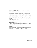
The
HP
8752C
vector
network
analyzer
integrates
a
high
resolution
synthesized
RF
source
,
transmission/reection
test
set,
and
a
dual
channel
three-input
receiver
to
measure
and
display
magnitude
,
phase
,
and
group
delay
of
transmitted
and
reected
power
.
The
HP
8752C
Option
010
has
the
additional
capability
of
transforming
measured
data
from
frequency
domain
to
time
domain.
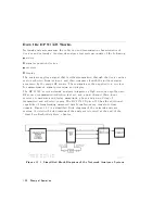
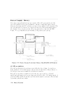
Figure
12-1
is
a
simplied
block
diagram
of
the
network
analyzer
system.
A
detailed
block
diagram
of
the
analyzer
is
located
at
the
end
of
the
\Start
Troubleshooting
Here"
chapter
.
Figure
12-1.
Simplied
Block
Diagram
of
the
Network
Analyzer
System
12-2
Theory
of
Operation
Summary of Contents for 8752C
Page 22: ...Before Applying Power 15 6 Servicing 15 6 Index Contents 16 ...
Page 38: ......
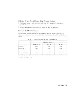
Page 43: ...Figure 2 1 Measurement Uncertainty Window System Veri cation and Performance Tests 2 5 ...
Page 116: ......
Page 122: ...Figure 3 1 Location of Major Assemblies 3 6 Adjustments and Correction Constants ...
Page 176: ......
Page 192: ...4 16 Start Troubleshooting Here ...
Page 193: ......
Page 195: ...Figure 4 7 HP 8752C Overall Block Diagram 3 of 4 Option 006 4 20 Start Troubleshooting Here ...
Page 197: ......
Page 221: ...5 24 Power Supply Troubleshooting ...
Page 222: ......
Page 271: ...Figure 7 21 A14 Generated Digital Control Signals Source Troubleshooting 7 31 ...
Page 302: ......
Page 366: ......
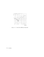
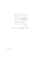
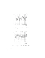
Page 378: ...Figure 11 4 Typical ED Re ection Test Port 11 12 Error Terms ...
Page 380: ...Figure 11 5 Typical ES Re ection Test Port 11 14 Error Terms ...
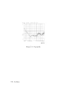
Page 382: ...Figure 11 6 Typical ER Re ection Test Port 11 16 Error Terms ...
Page 386: ...Figure 11 9 Typical ET 11 20 Error Terms ...
Page 407: ...Figure 12 5 High Band Operation of the Source Theory of Operation 12 21 ...
Page 410: ...Figure 12 6 Receiver Functional Group standard and Option 003 12 24 Theory of Operation ...
Page 411: ...Figure 12 7 Receiver Functional Group Option 003 and 004 Theory of Operation 12 25 ...
Page 412: ...Figure 12 8 Receiver Functional Group Option 006 12 26 Theory of Operation ...
Page 413: ...Figure 12 9 Receiver Functional Group Option 004 and 006 Theory of Operation 12 27 ...
Page 416: ......
Page 419: ...Figure 13 1 Module Exchange Procedure Replaceable Parts 13 3 ...
Page 423: ...Major Assemblies Replaceable Parts 13 7 ...
Page 425: ...Front Panel Assemblies Replaceable Parts 13 9 ...
Page 427: ...Rear Panel Assemblies Replaceable Parts 13 11 ...
Page 429: ...Cables Top View Replaceable Parts 13 13 ...
Page 431: ...Front Panel Cables and Attaching Hardware Replaceable Parts 13 15 ...
Page 433: ...Rear Panel Cables and Attaching Hardware Replaceable Parts 13 17 ...
Page 435: ...Source and Sampler Parts Standard and Option 003 Replaceable Parts 13 19 ...
Page 437: ...Source and Sampler Parts Option 004 006 Replaceable Parts 13 21 ...
Page 439: ...Source and Sampler Parts Options 004 and 003 004 Replaceable Parts 13 23 ...
Page 441: ...Source and Sampler Parts Option 006 Replaceable Parts 13 25 ...
Page 443: ...Display Bezel Assembly Replaceable Parts 13 27 ...
Page 445: ...Chassis Parts Replaceable Parts 13 29 ...
Page 447: ...Top View of Attaching Hardware and Post Regulator Fuses Replaceable Parts 13 31 ...
Page 449: ...Bottom View of Attaching Hardware Replaceable Parts 13 33 ...
Page 488: ......