


6.
Press
N
NNNNNNNNNNNNNNNNNNNNNNNNN
CONTINUE
to
run
the
\transmission
crosstalk,
noise
oor"
test.
(With
the
record
function
on,
this
test
will
automatically
run).
There
should
be
a
P
ASS/F
AIL
result
displayed
on
the
analyzer
.
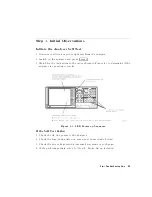
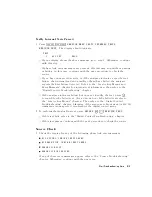
7.
Press
NNNNNNNNNNNNNNNNNNNNNNNNNN
CONTINUE
and
then
connect
the
RF
cable
supplied
with
the
analyzer
between
the
reection
and
transmission
test
ports
.
8.
Press
NNNNNNNNNNNNNNNNNNNNNNNNNN
CONTINUE
to
run
the
\transmission
tracking,
source/load
match"
test.
There
should
be
a
P
ASS/F
AIL
result
displayed
on
the
analyzer
.
9.
Press
N
NNNNNNNNNNNNNNNNNNNNNNNNN
CONTINUE
to
run
the
\load
match,
directivity"
test.
(With
the
record
function
on,
this
test
will
automatically
run.)
There
should
be
a
P
ASS/F
AIL
result
displayed
on
the
analyzer
.
10.
Press
NNNNNNNNNNNNNNNNNNNNNNNNNN
CONTINUE
again.
The
analyzer
now
displays
the
result
of
the
condence
test.
If
the
test
failed:
It
could
be
due
to
loose
connections
.
Tighten
all
connections
and
repeat
the
Condence
T
est.
It
could
be
due
to
a
bad
frequency
response
correction.
Run
service
test
53.
It
could
be
due
to
a
faulty
RF
cable
.
Run
the
cable
condence
test
(service
test
22)
or
replace
the
cable
.
Run
the
verication
procedure
(test
27)
to
identify
which
error
term
is
causing
the
failure
.
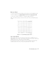
Cable
Condence
T
est
This
test
provides
an
easy
check
of
the
RF
performance
of
the
transmission
cable
supplied
with
the
HP
8752C.
The
test
limits
used
are
the
sum
of
the
HP
8752C
specications
that
apply
,
plus
the
uncertainties
in
the
measurement.
Procedure
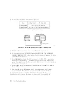
1.
Press
4
PRESET
5
4
SYSTEM
5
NNNNNNNNNNNNNNNNNNNNNNNNNNNNNNNNNNNNNN
SERVICE
MENU
NNNNNNNNNNNNNNNNN
TESTS
NNNNNNNNNNNNNNNNNNNNNNNNNNNNNNNNNNNNNNNNNNNN
EXTERNAL
TESTS
4
22
5
4
x1
5 .
The
analyzer
should
display:
TEST
22
CABLE
CONFID
-ND-
Start
T
roubleshooting
Here
4-5
Summary of Contents for 8752C
Page 22: ...Before Applying Power 15 6 Servicing 15 6 Index Contents 16 ...
Page 38: ......
Page 43: ...Figure 2 1 Measurement Uncertainty Window System Veri cation and Performance Tests 2 5 ...
Page 116: ......
Page 122: ...Figure 3 1 Location of Major Assemblies 3 6 Adjustments and Correction Constants ...
Page 176: ......
Page 192: ...4 16 Start Troubleshooting Here ...
Page 193: ......
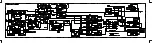
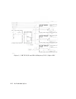
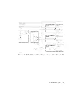
Page 195: ...Figure 4 7 HP 8752C Overall Block Diagram 3 of 4 Option 006 4 20 Start Troubleshooting Here ...
Page 197: ......
Page 221: ...5 24 Power Supply Troubleshooting ...
Page 222: ......
Page 271: ...Figure 7 21 A14 Generated Digital Control Signals Source Troubleshooting 7 31 ...
Page 302: ......
Page 366: ......
Page 378: ...Figure 11 4 Typical ED Re ection Test Port 11 12 Error Terms ...
Page 380: ...Figure 11 5 Typical ES Re ection Test Port 11 14 Error Terms ...
Page 382: ...Figure 11 6 Typical ER Re ection Test Port 11 16 Error Terms ...
Page 386: ...Figure 11 9 Typical ET 11 20 Error Terms ...
Page 407: ...Figure 12 5 High Band Operation of the Source Theory of Operation 12 21 ...
Page 410: ...Figure 12 6 Receiver Functional Group standard and Option 003 12 24 Theory of Operation ...
Page 411: ...Figure 12 7 Receiver Functional Group Option 003 and 004 Theory of Operation 12 25 ...
Page 412: ...Figure 12 8 Receiver Functional Group Option 006 12 26 Theory of Operation ...
Page 413: ...Figure 12 9 Receiver Functional Group Option 004 and 006 Theory of Operation 12 27 ...
Page 416: ......
Page 419: ...Figure 13 1 Module Exchange Procedure Replaceable Parts 13 3 ...
Page 423: ...Major Assemblies Replaceable Parts 13 7 ...
Page 425: ...Front Panel Assemblies Replaceable Parts 13 9 ...
Page 427: ...Rear Panel Assemblies Replaceable Parts 13 11 ...
Page 429: ...Cables Top View Replaceable Parts 13 13 ...
Page 431: ...Front Panel Cables and Attaching Hardware Replaceable Parts 13 15 ...
Page 433: ...Rear Panel Cables and Attaching Hardware Replaceable Parts 13 17 ...
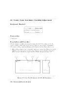
Page 435: ...Source and Sampler Parts Standard and Option 003 Replaceable Parts 13 19 ...
Page 437: ...Source and Sampler Parts Option 004 006 Replaceable Parts 13 21 ...
Page 439: ...Source and Sampler Parts Options 004 and 003 004 Replaceable Parts 13 23 ...
Page 441: ...Source and Sampler Parts Option 006 Replaceable Parts 13 25 ...
Page 443: ...Display Bezel Assembly Replaceable Parts 13 27 ...
Page 445: ...Chassis Parts Replaceable Parts 13 29 ...
Page 447: ...Top View of Attaching Hardware and Post Regulator Fuses Replaceable Parts 13 31 ...
Page 449: ...Bottom View of Attaching Hardware Replaceable Parts 13 33 ...
Page 488: ......