


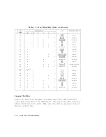


T
able
6-2.
Front
P
anel
K
ey
Codes
Decimal
Number
LED
P
attern
K
ey
Front
P
anel
Block
CH1
CH2
R
L
T
S
0
4
CAL
5
Response
1
4
3
5
Entry
2
4
k/m
5
Entry
3
4
DISPLA
Y
5
Response
4
4
A
VG
5
Response
5
4
2
5
Entry
6
4
1
5
Entry
7
?
??????????????????
softkey
3
Softkey
8
???????????????????
softkey
5
Softkey
9
4
9
5
Entry
10
4
G/n
5
Entry
11
4
CH
1
5
A
ctive
Channel
12
4
CH
2
5
A
ctive
Channel
13
4
8
5
Entry
14
4
7
5
Entry
15
?
??????????????????
softkey
1
Softkey
16
4
STOP
5
Stimulus
17
4
SA
VE/RECALL
5
Instrument
State
18
4
SEQ
5
Instrument
State
19
4
MENU
5
Stimulus
20
4
ST
ART
5
Stimulus
21
4
COPY
5
Instrument
State
22
4
SYSTEM
5
Instrument
State
23
???????????????????
softkey
6
Softkey
24
4
SCALE
REF
5
Response
25
4
6
5
Entry
Digital
Control
T
roubleshooting
6-9
Summary of Contents for 8752C
Page 22: ...Before Applying Power 15 6 Servicing 15 6 Index Contents 16 ...
Page 38: ......
Page 43: ...Figure 2 1 Measurement Uncertainty Window System Veri cation and Performance Tests 2 5 ...
Page 116: ......
Page 122: ...Figure 3 1 Location of Major Assemblies 3 6 Adjustments and Correction Constants ...
Page 176: ......
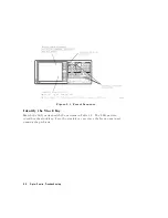
Page 192: ...4 16 Start Troubleshooting Here ...
Page 193: ......
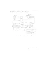
Page 195: ...Figure 4 7 HP 8752C Overall Block Diagram 3 of 4 Option 006 4 20 Start Troubleshooting Here ...
Page 197: ......
Page 221: ...5 24 Power Supply Troubleshooting ...
Page 222: ......
Page 271: ...Figure 7 21 A14 Generated Digital Control Signals Source Troubleshooting 7 31 ...
Page 302: ......
Page 366: ......
Page 378: ...Figure 11 4 Typical ED Re ection Test Port 11 12 Error Terms ...
Page 380: ...Figure 11 5 Typical ES Re ection Test Port 11 14 Error Terms ...
Page 382: ...Figure 11 6 Typical ER Re ection Test Port 11 16 Error Terms ...
Page 386: ...Figure 11 9 Typical ET 11 20 Error Terms ...
Page 407: ...Figure 12 5 High Band Operation of the Source Theory of Operation 12 21 ...
Page 410: ...Figure 12 6 Receiver Functional Group standard and Option 003 12 24 Theory of Operation ...
Page 411: ...Figure 12 7 Receiver Functional Group Option 003 and 004 Theory of Operation 12 25 ...
Page 412: ...Figure 12 8 Receiver Functional Group Option 006 12 26 Theory of Operation ...
Page 413: ...Figure 12 9 Receiver Functional Group Option 004 and 006 Theory of Operation 12 27 ...
Page 416: ......
Page 419: ...Figure 13 1 Module Exchange Procedure Replaceable Parts 13 3 ...
Page 423: ...Major Assemblies Replaceable Parts 13 7 ...
Page 425: ...Front Panel Assemblies Replaceable Parts 13 9 ...
Page 427: ...Rear Panel Assemblies Replaceable Parts 13 11 ...
Page 429: ...Cables Top View Replaceable Parts 13 13 ...
Page 431: ...Front Panel Cables and Attaching Hardware Replaceable Parts 13 15 ...
Page 433: ...Rear Panel Cables and Attaching Hardware Replaceable Parts 13 17 ...
Page 435: ...Source and Sampler Parts Standard and Option 003 Replaceable Parts 13 19 ...
Page 437: ...Source and Sampler Parts Option 004 006 Replaceable Parts 13 21 ...
Page 439: ...Source and Sampler Parts Options 004 and 003 004 Replaceable Parts 13 23 ...
Page 441: ...Source and Sampler Parts Option 006 Replaceable Parts 13 25 ...
Page 443: ...Display Bezel Assembly Replaceable Parts 13 27 ...
Page 445: ...Chassis Parts Replaceable Parts 13 29 ...
Page 447: ...Top View of Attaching Hardware and Post Regulator Fuses Replaceable Parts 13 31 ...
Page 449: ...Bottom View of Attaching Hardware Replaceable Parts 13 33 ...
Page 488: ......