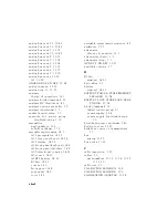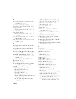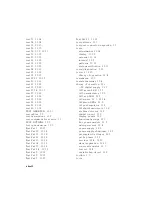
removal,
14-12
theory
of
operation,
12-6
preregulator
LEDs
check,
4-11
preregulator
voltages,
5-9
PRESET,
10-7
preset
sequence,
4-3,
6-8
Pretune
Cor
.,
10-14
Pretune
Def.,
10-14
preventive
maintenance,
11-2
principles
of
microwave
connector
care,
1-5
printer,
1-3
PRINTER
not
on,
not
connected,
wrong
addrs,
10-61
printer
HP-IB
address,
4-7
probe
power,
12-9
probe
(photometer),
1-3
PROBE
POWER
SHUT
DOWN!,
10-62
probe
power
voltages,
5-19
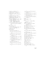
procedures
A9
CC
Jumper
P
osition
A
djustment,
3-5
ADC
Oset
Correction
Constants
(T
est
#52),
3-21
Analog
Bus
Correction
Constants
(T
est
#46),
3-10
Cavity
Oscillator
Frequency
Correction
Constants
(T
est
#54),
3-24
Display
Degaussing
(Demagnetizing),
3-45
Display
Intensity
A
djustments
(T
est
#49),
3-15
EEPROM
Backup
Disk
Procedure,
3-38
Fractional-N
Frequency
Range
A
djustment,
3-46
Fractional-N
Spur
A
voidance
and
FM
Sideband
A
djustment,
3-54
Frequency
A
ccuracy
A
djustment,
3-49
Frequency
Response
Correction
Constants
(T
ests
#53
and
#57),
3-22
High/Low
Band
Transition
A
djustment,
3-51
IF
Amplier
Correction
Constants
(T
est
#51),
3-19
Initialize
EEPROMs
(T
est
58),
3-37
Model
Number
Correction
Constant
(Option
075
Only),
3-42
Option
Numbers
Correction
Constant
(T
est
#56),
3-34
RF
Output
P
ower
Correction
Constants
(T
est
#47),
3-11
Serial
Number
Correction
Constant
(T
est
#55),
3-32
Source
Default
Correction
Constants
(T
est
#44),
3-8
Source
Pretune
Correction
Constants
(T
est
#48),
3-14
Source
Pretune
Default
Correction
Constants
(T
est
#45),
3-9
Source
Spur
A
voidance
Tracking
A
djustment,
3-58
V
ertical
P
osition
and
F
ocus
A
djustments,
3-43
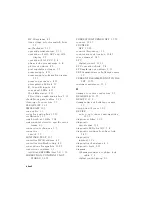
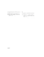
pulse
generator
source,
12-14
pulse
generator
(A7)
check,
7-33
pulses
(100
kHz),
7-16
R
R,
A,
and
B
inputs
check,
8-4
rear
panel
digital
control,
12-13
part
numbers,
13-10
Rear
P
anel,
10-10
rear
panel
board
removal,
14-14
Index-16
Summary of Contents for 8752C
Page 22: ...Before Applying Power 15 6 Servicing 15 6 Index Contents 16 ...
Page 38: ......
Page 43: ...Figure 2 1 Measurement Uncertainty Window System Veri cation and Performance Tests 2 5 ...
Page 116: ......
Page 122: ...Figure 3 1 Location of Major Assemblies 3 6 Adjustments and Correction Constants ...
Page 176: ......
Page 192: ...4 16 Start Troubleshooting Here ...
Page 193: ......
Page 195: ...Figure 4 7 HP 8752C Overall Block Diagram 3 of 4 Option 006 4 20 Start Troubleshooting Here ...
Page 197: ......
Page 221: ...5 24 Power Supply Troubleshooting ...
Page 222: ......
Page 271: ...Figure 7 21 A14 Generated Digital Control Signals Source Troubleshooting 7 31 ...
Page 302: ......
Page 366: ......
Page 378: ...Figure 11 4 Typical ED Re ection Test Port 11 12 Error Terms ...
Page 380: ...Figure 11 5 Typical ES Re ection Test Port 11 14 Error Terms ...
Page 382: ...Figure 11 6 Typical ER Re ection Test Port 11 16 Error Terms ...
Page 386: ...Figure 11 9 Typical ET 11 20 Error Terms ...
Page 407: ...Figure 12 5 High Band Operation of the Source Theory of Operation 12 21 ...
Page 410: ...Figure 12 6 Receiver Functional Group standard and Option 003 12 24 Theory of Operation ...
Page 411: ...Figure 12 7 Receiver Functional Group Option 003 and 004 Theory of Operation 12 25 ...
Page 412: ...Figure 12 8 Receiver Functional Group Option 006 12 26 Theory of Operation ...
Page 413: ...Figure 12 9 Receiver Functional Group Option 004 and 006 Theory of Operation 12 27 ...
Page 416: ......
Page 419: ...Figure 13 1 Module Exchange Procedure Replaceable Parts 13 3 ...
Page 423: ...Major Assemblies Replaceable Parts 13 7 ...
Page 425: ...Front Panel Assemblies Replaceable Parts 13 9 ...
Page 427: ...Rear Panel Assemblies Replaceable Parts 13 11 ...
Page 429: ...Cables Top View Replaceable Parts 13 13 ...
Page 431: ...Front Panel Cables and Attaching Hardware Replaceable Parts 13 15 ...
Page 433: ...Rear Panel Cables and Attaching Hardware Replaceable Parts 13 17 ...
Page 435: ...Source and Sampler Parts Standard and Option 003 Replaceable Parts 13 19 ...
Page 437: ...Source and Sampler Parts Option 004 006 Replaceable Parts 13 21 ...
Page 439: ...Source and Sampler Parts Options 004 and 003 004 Replaceable Parts 13 23 ...
Page 441: ...Source and Sampler Parts Option 006 Replaceable Parts 13 25 ...
Page 443: ...Display Bezel Assembly Replaceable Parts 13 27 ...
Page 445: ...Chassis Parts Replaceable Parts 13 29 ...
Page 447: ...Top View of Attaching Hardware and Post Regulator Fuses Replaceable Parts 13 31 ...
Page 449: ...Bottom View of Attaching Hardware Replaceable Parts 13 33 ...
Page 488: ......


