


Step
2.
Condence
T
est
The
condence
test
veries
that
the
circuits
in
the
analyzer
are
functioning
properly
.
However
,
it
does
not
verify
the
accessories
or
the
analyzer
specications
.
The
resulting
measurement
must
fall
within
a
limit
testing
window
to
pass
the
test.
The
window
size
is
based
on
both
source
and
receiver
specications
.
The
characteristics
tested
are
combinations
of:
source
match,
reection
tracking,
directivity
,
transmission
tracking,
noise
oor
,
and
crosstalk.
The
condence
test
adds
all
the
applicable
error
terms
together
.
T
o
separate
them
out
or
to
keep
a
record
of
them
for
maintenance
,
refer
to
the
\Error
T
erms"
chapter
.
If
you
want
to
test
the
individual
analyzer
specications
then
refer
to
the
\V
erication
and
P
erformance
T
ests"
chapter
.
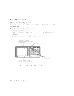
Procedure
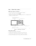
1.
Select
the
test
data
printing
status
.
If
you
do
not
want
the
test
data
to
automatically
print,
continue
with
step
2.
If
you
want
to
have
the
test
data
automatically
print,
press
4
PRESET
5
4
SYSTEM
5
NNNNNNNNNNNNNNNNNNNNNNNNNNNNNNNNNNNNNN
SERVICE
MENU
NNNNNNNNNNNNNNNNNNNNNNNNNNNNNNNNNNNNNN
TEST
OPTIONS
NNNNNNNNNNNNNNNNNNNNNNNNNNNNN
RECORD
ON
.
Note
When
using
an
InkJet
printer
,
the
analyzer
must
be
set
to
the
standard
mode
through
the
4
COPY
5
menu.
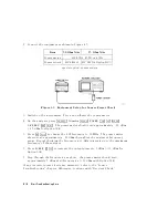
2.
Press
4
SYSTEM
5
NNNNNNNNNNNNNNNNNNNNNNNNNNNNNNNNNNNNNN
SERVICE
MENU
NNNNNNNNNNNNNNNNN
TESTS
NNNNNNNNNNNNNNNNNNNNNNNNNNNNNNNNNNNNNNNNNNNN
EXTERNAL
TESTS
NNNNNNNNNNNNNNNNNNNNNNNNNNNNNNNNNNNNNN
EXECUTE
TEST
.
The
analyzer
should
display
a
short
description
of
the
test
and
a
reminder
of
the
RECORD
function.
3.
Press
NNNNNNNNNNNNNNNNNNNNNNNNNN
CONTINUE
to
begin
the
test.
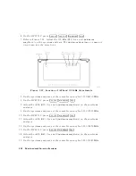
4.
Disconnect
all
devices
from
the
reection
test
port,
as
prompted
on
the
analyzer
display
.
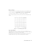
5.
Press
N
NNNNNNNNNNNNNNNNNNNNNNNNN
CONTINUE
to
run
the
\source
match,
tracking"
test.
There
should
be
a
P
ASS/F
AIL
result
displayed
on
the
analyzer
.
4-4
Start
T
roubleshooting
Here
Summary of Contents for 8752C
Page 22: ...Before Applying Power 15 6 Servicing 15 6 Index Contents 16 ...
Page 38: ......
Page 43: ...Figure 2 1 Measurement Uncertainty Window System Veri cation and Performance Tests 2 5 ...
Page 116: ......
Page 122: ...Figure 3 1 Location of Major Assemblies 3 6 Adjustments and Correction Constants ...
Page 176: ......
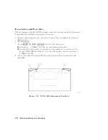
Page 192: ...4 16 Start Troubleshooting Here ...
Page 193: ......
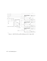
Page 195: ...Figure 4 7 HP 8752C Overall Block Diagram 3 of 4 Option 006 4 20 Start Troubleshooting Here ...
Page 197: ......
Page 221: ...5 24 Power Supply Troubleshooting ...
Page 222: ......
Page 271: ...Figure 7 21 A14 Generated Digital Control Signals Source Troubleshooting 7 31 ...
Page 302: ......
Page 366: ......
Page 378: ...Figure 11 4 Typical ED Re ection Test Port 11 12 Error Terms ...
Page 380: ...Figure 11 5 Typical ES Re ection Test Port 11 14 Error Terms ...
Page 382: ...Figure 11 6 Typical ER Re ection Test Port 11 16 Error Terms ...
Page 386: ...Figure 11 9 Typical ET 11 20 Error Terms ...
Page 407: ...Figure 12 5 High Band Operation of the Source Theory of Operation 12 21 ...
Page 410: ...Figure 12 6 Receiver Functional Group standard and Option 003 12 24 Theory of Operation ...
Page 411: ...Figure 12 7 Receiver Functional Group Option 003 and 004 Theory of Operation 12 25 ...
Page 412: ...Figure 12 8 Receiver Functional Group Option 006 12 26 Theory of Operation ...
Page 413: ...Figure 12 9 Receiver Functional Group Option 004 and 006 Theory of Operation 12 27 ...
Page 416: ......
Page 419: ...Figure 13 1 Module Exchange Procedure Replaceable Parts 13 3 ...
Page 423: ...Major Assemblies Replaceable Parts 13 7 ...
Page 425: ...Front Panel Assemblies Replaceable Parts 13 9 ...
Page 427: ...Rear Panel Assemblies Replaceable Parts 13 11 ...
Page 429: ...Cables Top View Replaceable Parts 13 13 ...
Page 431: ...Front Panel Cables and Attaching Hardware Replaceable Parts 13 15 ...
Page 433: ...Rear Panel Cables and Attaching Hardware Replaceable Parts 13 17 ...
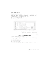
Page 435: ...Source and Sampler Parts Standard and Option 003 Replaceable Parts 13 19 ...
Page 437: ...Source and Sampler Parts Option 004 006 Replaceable Parts 13 21 ...
Page 439: ...Source and Sampler Parts Options 004 and 003 004 Replaceable Parts 13 23 ...
Page 441: ...Source and Sampler Parts Option 006 Replaceable Parts 13 25 ...
Page 443: ...Display Bezel Assembly Replaceable Parts 13 27 ...
Page 445: ...Chassis Parts Replaceable Parts 13 29 ...
Page 447: ...Top View of Attaching Hardware and Post Regulator Fuses Replaceable Parts 13 31 ...
Page 449: ...Bottom View of Attaching Hardware Replaceable Parts 13 33 ...
Page 488: ......