


22.
Fractional-N
Spur
A
voidance
and
FM
Sideband
A
djustment
Equipment
Required
Item
HP
Model
Number
Spectrum
Analyzer
HP
8563E
RF
Cable
50,
type-N,
24-inch
HP
P/N
8120-4781
Cable
,
50
Coax,
BNC
(m)
to
BNC
(m)
HP
10503A
Non-metallic
A
djustment
T
ool
HP
P/N
8830-0024
Antistatic
Wrist
Strap
HP
P/N
9300-1367
Antistatic
Wrist
Strap
Cord
HP
P/N
9300-0980
Static-control
T
able
Mat
and
Earth
Ground
Wire
HP
P/N
9300-0797
50
to
75
Minimum
Loss
P
ad
*
HP
11852B
*
Option
075
analyzers
only
.
W
armup
time
30
minutes
Description
and
Procedure
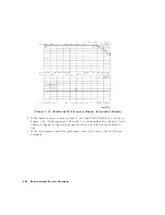
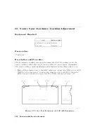
This
adjustment
minimizes
the
spurs
caused
by
the
API
(analog
phase
interpolator
,
on
the
fractional-N
assembly)
circuits
.
It
also
improves
the
sideband
characteristics
.
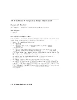
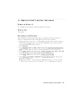
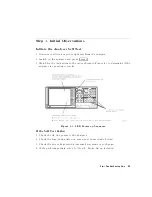
1.
Connect
the
equipment
as
shown
in
Figure
3-21 .
2.
Make
sure
the
instruments
are
set
to
their
default
HP-IB
addresses:
HP
8752C
=
16,
Spectrum
Analyzer
=
18.
3-54
Adjustments
and
Correction
Constants
Summary of Contents for 8752C
Page 22: ...Before Applying Power 15 6 Servicing 15 6 Index Contents 16 ...
Page 38: ......
Page 43: ...Figure 2 1 Measurement Uncertainty Window System Veri cation and Performance Tests 2 5 ...
Page 116: ......
Page 122: ...Figure 3 1 Location of Major Assemblies 3 6 Adjustments and Correction Constants ...
Page 176: ......
Page 192: ...4 16 Start Troubleshooting Here ...
Page 193: ......
Page 195: ...Figure 4 7 HP 8752C Overall Block Diagram 3 of 4 Option 006 4 20 Start Troubleshooting Here ...
Page 197: ......
Page 221: ...5 24 Power Supply Troubleshooting ...
Page 222: ......
Page 271: ...Figure 7 21 A14 Generated Digital Control Signals Source Troubleshooting 7 31 ...
Page 302: ......
Page 366: ......
Page 378: ...Figure 11 4 Typical ED Re ection Test Port 11 12 Error Terms ...
Page 380: ...Figure 11 5 Typical ES Re ection Test Port 11 14 Error Terms ...
Page 382: ...Figure 11 6 Typical ER Re ection Test Port 11 16 Error Terms ...
Page 386: ...Figure 11 9 Typical ET 11 20 Error Terms ...
Page 407: ...Figure 12 5 High Band Operation of the Source Theory of Operation 12 21 ...
Page 410: ...Figure 12 6 Receiver Functional Group standard and Option 003 12 24 Theory of Operation ...
Page 411: ...Figure 12 7 Receiver Functional Group Option 003 and 004 Theory of Operation 12 25 ...
Page 412: ...Figure 12 8 Receiver Functional Group Option 006 12 26 Theory of Operation ...
Page 413: ...Figure 12 9 Receiver Functional Group Option 004 and 006 Theory of Operation 12 27 ...
Page 416: ......
Page 419: ...Figure 13 1 Module Exchange Procedure Replaceable Parts 13 3 ...
Page 423: ...Major Assemblies Replaceable Parts 13 7 ...
Page 425: ...Front Panel Assemblies Replaceable Parts 13 9 ...
Page 427: ...Rear Panel Assemblies Replaceable Parts 13 11 ...
Page 429: ...Cables Top View Replaceable Parts 13 13 ...
Page 431: ...Front Panel Cables and Attaching Hardware Replaceable Parts 13 15 ...
Page 433: ...Rear Panel Cables and Attaching Hardware Replaceable Parts 13 17 ...
Page 435: ...Source and Sampler Parts Standard and Option 003 Replaceable Parts 13 19 ...
Page 437: ...Source and Sampler Parts Option 004 006 Replaceable Parts 13 21 ...
Page 439: ...Source and Sampler Parts Options 004 and 003 004 Replaceable Parts 13 23 ...
Page 441: ...Source and Sampler Parts Option 006 Replaceable Parts 13 25 ...
Page 443: ...Display Bezel Assembly Replaceable Parts 13 27 ...
Page 445: ...Chassis Parts Replaceable Parts 13 29 ...
Page 447: ...Top View of Attaching Hardware and Post Regulator Fuses Replaceable Parts 13 31 ...
Page 449: ...Bottom View of Attaching Hardware Replaceable Parts 13 33 ...
Page 488: ......