


DISK
READ/WRITE
ERROR
Error
Number
189
There
may
be
a
problem
with
your
disk.
Try
a
new
oppy
disk.
If
a
new
oppy
disk
does
not
eliminate
the
error
,
suspect
hardware
problems
.
INITIALIZATION
FAILED
Error
Number
47
The
disk
initialization
failed,
probably
because
the
disk
is
damaged.
NO
CALIBRATION
CURRENTLY
IN
PROGRESS
Error
Number
69
The
NNNNNNNNNNNNNNNNNNNNNNNNNNNNNNNNNNNNNNNNNNNNNNNNNNNNNNNNNNN
RESUME
CAL
SEQUENCE
softkey
is
not
valid
unless
a
calibration
is
already
in
progress
.
Start
a
new
calibration.
NOT
ENOUGH
SPACE
ON
DISK
FOR
STORE
Error
Number
44
The
store
operation
will
overow
the
available
disk
space
.
Insert
a
new
disk
or
purge
les
to
create
free
disk
space
.
NO
FILE(S)
FOUND
ON
DISK
Error
Number
45
No
les
of
the
type
created
by
an
analyzer
store
operation
were
found
on
the
disk.
If
you
requested
a
specic
le
title
,
that
le
was
not
found
on
the
disk.
Service
K
ey
Menus
and
Error
Messages
10-57
Summary of Contents for 8752C
Page 22: ...Before Applying Power 15 6 Servicing 15 6 Index Contents 16 ...
Page 38: ......
Page 43: ...Figure 2 1 Measurement Uncertainty Window System Veri cation and Performance Tests 2 5 ...
Page 116: ......
Page 122: ...Figure 3 1 Location of Major Assemblies 3 6 Adjustments and Correction Constants ...
Page 176: ......
Page 192: ...4 16 Start Troubleshooting Here ...
Page 193: ......
Page 195: ...Figure 4 7 HP 8752C Overall Block Diagram 3 of 4 Option 006 4 20 Start Troubleshooting Here ...
Page 197: ......
Page 221: ...5 24 Power Supply Troubleshooting ...
Page 222: ......
Page 271: ...Figure 7 21 A14 Generated Digital Control Signals Source Troubleshooting 7 31 ...
Page 302: ......
Page 366: ......
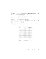
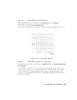
Page 378: ...Figure 11 4 Typical ED Re ection Test Port 11 12 Error Terms ...
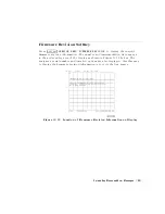
Page 380: ...Figure 11 5 Typical ES Re ection Test Port 11 14 Error Terms ...
Page 382: ...Figure 11 6 Typical ER Re ection Test Port 11 16 Error Terms ...
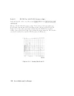
Page 386: ...Figure 11 9 Typical ET 11 20 Error Terms ...
Page 407: ...Figure 12 5 High Band Operation of the Source Theory of Operation 12 21 ...
Page 410: ...Figure 12 6 Receiver Functional Group standard and Option 003 12 24 Theory of Operation ...
Page 411: ...Figure 12 7 Receiver Functional Group Option 003 and 004 Theory of Operation 12 25 ...
Page 412: ...Figure 12 8 Receiver Functional Group Option 006 12 26 Theory of Operation ...
Page 413: ...Figure 12 9 Receiver Functional Group Option 004 and 006 Theory of Operation 12 27 ...
Page 416: ......
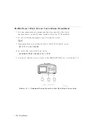
Page 419: ...Figure 13 1 Module Exchange Procedure Replaceable Parts 13 3 ...
Page 423: ...Major Assemblies Replaceable Parts 13 7 ...
Page 425: ...Front Panel Assemblies Replaceable Parts 13 9 ...
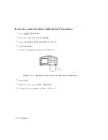
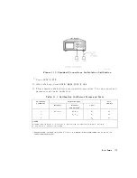
Page 427: ...Rear Panel Assemblies Replaceable Parts 13 11 ...
Page 429: ...Cables Top View Replaceable Parts 13 13 ...
Page 431: ...Front Panel Cables and Attaching Hardware Replaceable Parts 13 15 ...
Page 433: ...Rear Panel Cables and Attaching Hardware Replaceable Parts 13 17 ...
Page 435: ...Source and Sampler Parts Standard and Option 003 Replaceable Parts 13 19 ...
Page 437: ...Source and Sampler Parts Option 004 006 Replaceable Parts 13 21 ...
Page 439: ...Source and Sampler Parts Options 004 and 003 004 Replaceable Parts 13 23 ...
Page 441: ...Source and Sampler Parts Option 006 Replaceable Parts 13 25 ...
Page 443: ...Display Bezel Assembly Replaceable Parts 13 27 ...
Page 445: ...Chassis Parts Replaceable Parts 13 29 ...
Page 447: ...Top View of Attaching Hardware and Post Regulator Fuses Replaceable Parts 13 31 ...
Page 449: ...Bottom View of Attaching Hardware Replaceable Parts 13 33 ...
Page 488: ......