22
5. Carefully slide the rudder onto each hinge and
against the trailing edge of the fin. Wipe away
excess epoxy with alcohol wetted wipes.
6. Ensure there is no gap between fin and rudder.
Allow epoxy to fully cure. Check you have full
rudder deflection before epoxy fully cures.
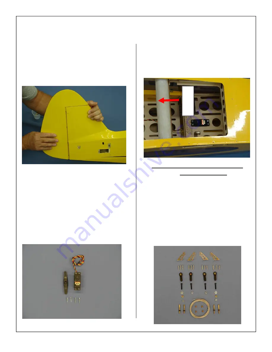
7. Gather the following items for the rudder servo
installation.
◊
1 - rudder servo
◊
4 - mounting screws
◊
1 - 2 3/4” double output arm
Note:
180 in. oz. digital, metal geared servo is
recommended. Servo selection can be the
difference between a great flying model and a
model that will crash. Always use brand name
high
quality
servos.
8. Install the rudder servo in the servo cutout with
the output shaft to the front.
Note:
Remove balsa stick holding the elevator pull
strings at this time. Secure the pull strings with
tape until the elevator extensions are installed.
Rudder Horn, Pull-Pull Cable and
Servo Installation
1. Gather the rudder control linkage parts shown
below.
◊
2 - Rudder cables
◊
4 - Ball link assemblies
◊
2 - Flat washers
◊
2 - Brass Spacers
◊
4 - Threaded couplers with lock nut
◊
4 - Brass swaging tubes
◊
2 - Left side control horns
◊
2 - Right side control horns
◊
12 - Wood screws
FRONT


