Revision: 4.08.00
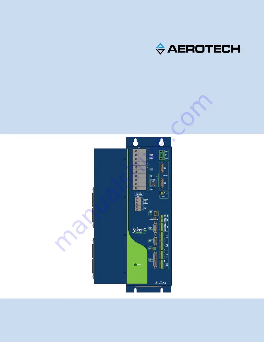
Soloist HPe 150/200 Hardware
Manual
Page 1: ...Revision 4 08 00 Soloist HPe 150 200 Hardware Manual...
Page 2: ...ech com Phone 1 412 967 6440 Fax 1 412 967 6870 101 Zeta Drive Pittsburgh PA 15238 2811 www aerotech com United Kingdom China Email Support aerotech com Phone 44 0 1256 855055 Fax 44 0 1256 855649 Ema...
Page 3: ...ions 32 2 2 2 1 DC Brush Motor Phasing 33 2 2 3 Stepper Motor Connections 34 2 2 3 1 Stepper Motor Phasing 35 2 3 Motor Feedback Connections J207 36 2 3 1 Encoder Interface J207 37 2 3 1 1 RS 422 Line...
Page 4: ...05 TB306 77 3 6 Opto In Connecter Digital Inputs TB305 TB306 78 3 7 Opto Out Connector Digital Outputs TB307 TB308 81 Chapter 4 RDP Expansion Board 85 Chapter 5 Standard Interconnection Cables 89 5 1...
Page 5: ...J207 48 Figure 2 22 Limit Input Diagnostic Display 49 Figure 2 23 ESTOP Sense Input TB201 51 Figure 2 24 Typical Emergency Stop Circuit 52 Figure 2 25 Auxiliary Encoder Channel J205 55 Figure 2 26 PS...
Page 6: ...s 88 Figure 5 1 Single Axis Joystick Interface to Aux I O 90 Figure 5 2 Two Axis Joystick Interface to the Aux I O of two drives 91 Figure 5 3 Two Axis Joystick Interface to the Aux I O and I O Board...
Page 7: ...8 Mating Connector Part Numbers for the ESTOP Connector TB201 51 Table 2 19 Typical ESTOP Relay Ratings 52 Table 2 20 Auxiliary I O Connector Pinout J205 53 Table 2 21 Mating Connector Part Numbers fo...
Page 8: ...Table 3 17 User Common Pin on the Opto In Connector TB305 77 Table 3 18 5 Volt Power Pin on the Opto In Connector TB306 77 Table 3 19 Digital Input Device Specifications 78 Table 3 20 Port 1 Opto In C...
Page 9: ...tive and has been designed to be in conformity with the applicable requirements of the following Standard s when installed and used in accordance with the manufacturer s supplied installation instruct...
Page 10: ...ication CUS NRTL Approving Agency TUV SUD America Inc Certificate U8 17 01 68995 023 Standards CAN CSA C22 2 No 61010 1 2012 UL 61010 1 2012 Visit https www tuev sued de product testing certificates t...
Page 11: ...on D A N G E R This product contains potentially lethal voltages To reduce the possibility of electrical shock bodily injury or death the following precautions must be followed 1 Disconnect electrical...
Page 12: ...ng injuries Access to all stage and motor parts must be restricted while connected to a power source 3 Cables can pose a tripping hazard Securely mount and position all system cables to avoid potentia...
Page 13: ...on your Sales Order under the heading Integration that drawing can be found on your installation device Figure 1 Quick Start Connections Topic Section Motor Output Section 2 2 Motor Output Connections...
Page 14: ...Soloist HPe 150 200 Quick Installation Guide 14 www aerotech com This page intentionally left blank...
Page 15: ...l PID and current loops All system configuration is done using software settable parameters including control loop gains and system safety functions The Soloist HPe 150 200 is offered with an optional...
Page 16: ...elp file l Camming Refer to the Help file l 10 100 BASE T Ethernet port for use with Ethernet I O modules Refer to the Help file Table 1 2 Ordering Options Options Power Stage Options Section 1 2 150...
Page 17: ...h the drive must be returned to Aerotech if firmware calibration updates are required read write access to parameters and programs is supported Resolver Options Chapter 4 RDP1 10K One channel resolver...
Page 18: ...er 1 www aerotech com The following block diagram shows a connection summary For detailed connection information refer to Chapter 2 and Chapter 3 Figure 1 2 Functional Diagram Soloist HPe 150 200 Intr...
Page 19: ...n of the software first supported the drive Drives that list a specific version number in the Last Software Version column will not be supported after the listed version Table 1 5 Drive and Software C...
Page 20: ...75 A 75 A Power Amplifier Bandwidth 2500 Hz maximum software selectable Power Amplifier Efficiency 85 95 2 PWM Switching Frequency 20 kHz Minimum Load Inductance 0 8 mH 160 VDC 1 mH 320 VDC User Powe...
Page 21: ...electronics or power transformer An EfficiencyFactor of approximately 90 should be used in the following equations Brushless Motor Output Power Rotary Motors Pout W Torque N m Angular velocity rad sec...
Page 22: ...d be separated from other drives and surrounded by 25 mm 1 of free air space A space of 100 mm 4 should be allowed along the front of the unit for cable connections Figure 1 3 Dimensions Table 1 7 Phy...
Page 23: ...mperature Operating 0 to 50 C 32 to 122 F Storage 30 to 85 C 22 to 185 F Humidity Maximum relative humidity is 80 for temperatures up to 31 C Decreasing linearly to 50 relative humidity at 40 C Non co...
Page 24: ...Soloist HPe 150 200 Introduction 24 Chapter 1 www aerotech com This page intentionally left blank...
Page 25: ...gency Stop condition The control power supply requires a minimum of 85 VAC input to operate properly The AC1 input is internally fused The AC2 input is not internally fused but can be connected to a v...
Page 26: ...es or circuit breakers l The recommended wire size is 8 34 mm2 8 AWG l External fuses or a circuit breaker 60 A maximum time delay type are required for the AC1 AC2 and AC3 inputs Power for the coolin...
Page 27: ...to radiated emission standards The Soloist HPe 150 200 is a component designed to be integrated with other electronics EMC testing must be conducted on the final product configuration Ferrite beads ca...
Page 28: ...tepper see Section 2 2 3 For a complete list of electrical specifications refer to Section 1 2 Table 2 3 Motor Power Output Connections Pin Description Recommended Wire Size A Phase A Motor Lead 13 3...
Page 29: ...res Green White indicates a single wire N OTE Brushless motors are commutated electronically by the controller The use of Hall effect devices for commutation is recommended The controller requires tha...
Page 30: ...2 2 1 1 Powered Motor Phasing Refer to the Motor Phasing Calculator in the Configuration Manager for motor Hall and encoder phasing Figure 2 4 Encoder and Hall Signal Diagnostics Soloist HPe 150 200 I...
Page 31: ...he positive direction Figure 2 5 Motor Phasing Oscilloscope Example With the designations of the motor and Hall leads of a third party motor determined the motor can now be connected to an Aerotech sy...
Page 32: ...onfiguration Table 2 5 Wire Colors for Aerotech Supplied Cables DC Brush Pin Wire Color Set 1 1 Wire Color Set 2 Wire Color Set 3 Green White Shield 2 Green Yellow Shield Green Yellow Shield A Red Ora...
Page 33: ...ive lead of the voltmeter to the other motor terminal 3 Rotate the motor clockwise by hand Figure 2 8 Clockwise Motor Rotation 4 If the voltmeter indicates a negative value swap the motor leads and ro...
Page 34: ...For example an 80V motor bus supply is needed to get 40V across the motor Figure 2 9 Stepper Motor Configuration Table 2 6 Wire Colors for Aerotech Supplied Cables Stepper Pin Wire Color Set 1 1 Wire...
Page 35: ...ion as viewed looking at the motor from the front mounting flange the motor is phased correctly If the motor moves in a counterclockwise direction swap the motor leads and re run the command Proper mo...
Page 36: ...eference Pulse Input Absolute Encoder Interface Clock Output 8 Absolute Encoder Interface Data Bidirectional 9 Reserved N A 10 Hall Effect Sensor A brushless motors only Input 11 Hall Effect Sensor C...
Page 37: ...er settings Refer to Section 2 3 1 4 for encoder feedback phasing Refer to Section 2 5 for the auxiliary encoder channel N OTE Encoder wiring should be physically isolated from motor AC power and all...
Page 38: ...use a feedback fault when the axis is enabled An analog encoder is used with the MXH option refer to Section 2 3 1 3 for more information Table 2 10 Encoder Specifications Specification Value Encoder...
Page 39: ...der fault information via a serial data stream from the absolute encoder See Figure 2 12 for the serial data stream interface Refer to the Help file for information on how to set up your EnDat or Reso...
Page 40: ...re output Refer to Figure 2 13 for the typical input circuitry The encoder interface pin assignment is indicated in Section 2 3 1 The gain offset and phase balance of the analog Sine and Cosine encode...
Page 41: ...Installation and Configuration Soloist HPe 150 200 Figure 2 14 Analog Encoder Interface J207 www aerotech com Chapter 2 41...
Page 42: ...hile observing the position of the encoder in the diagnostics display see Figure 2 16 The Motor Phasing Calculator in the Configuration Manager can be used to determine proper encoder polarity For dua...
Page 43: ...Installation and Configuration Soloist HPe 150 200 Figure 2 16 Position Feedback in the Diagnostic Display www aerotech com Chapter 2 43...
Page 44: ...efer to Section 2 2 1 1 for Hall effect device phasing Table 2 12 Hall Effect Feedback Interface Pins on the Motor Feedback Connector J207 Pin Description In Out Bi 1 Chassis Frame Ground N A 3 5V Pow...
Page 45: ...the resistance of the thermistor is low i e 100 ohms which will result in a low input signal As the increasing temperature causes the thermistor s resistance to increase the signal will be seen as a l...
Page 46: ...of encoder function The active state of this input is parameter configurable and the controller should be configured to disable the axis when the fault level is active Table 2 14 Encoder Fault Interf...
Page 47: ...input Negative motion is stopped by the counterclockwise CCW end of travel limit input The Home Limit switch can be parameter configured for use during the home cycle however the CW or CCW EOT limit...
Page 48: ...48 Chapter 2 www aerotech com Figure 2 21 End of Travel Limit Interface Input J207 Soloist HPe 150 200 Installation and Configuration...
Page 49: ...able to move further into a limit but be unable to move out To correct this swap the connections to the CW and CCW inputs at the motor feedback connector The logic level of the EOT limit inputs may b...
Page 50: ...ist Help file for more information Use either the solid state relay on the Soloist HPe 150 200 or the mechanical relay on the IO board when connecting a power supply to the brake outputs on J207 Do no...
Page 51: ...Figure 2 24 for interconnection details The ESTOP input is scaled for an input voltage of 5 24 volts If the ESTOP bit is enabled in the FaultMask axis parameter the ESTOP input must be driven to prev...
Page 52: ...power as shown in the Figure 2 24 The external relay must be sized based on the number of the Soloist HPe 150 200s connected and the peak current rating of each drive Figure 2 24 Typical Emergency Sto...
Page 53: ...iary Cosine Bidirectional 12 5 Volt 500 mA max Output 13 Analog Input 0 Differential Input 14 Analog Input 0 Differential Input 15 Output Common 16 Digital Output 3 Output 17 Digital Input 0 CCW EOT I...
Page 54: ...2 22 Auxiliary Encoder Specifications Specification Value Encoder Frequency 10 MHz maximum 25 nsec minimum edge separation x4 Quadrature Decoding 40 million counts sec N OTE Use the EncoderDivider par...
Page 55: ...Installation and Configuration Soloist HPe 150 200 Figure 2 25 Auxiliary Encoder Channel J205 www aerotech com Chapter 2 55...
Page 56: ...ceiver or opto isolator is recommended especially when using long cable lengths in noisy environments or when high frequency pulse transmission is required It is best to locate the line receiver or op...
Page 57: ...Installation and Configuration Soloist HPe 150 200 Figure 2 26 PSO Interface www aerotech com Chapter 2 57...
Page 58: ...s common connections can be directly connected to the drive s power supply however doing so will effectively defeat the isolation and will reduce noise immunity Table 2 26 Digital Output Specification...
Page 59: ...HPe 150 200 N OTE Outputs must be connected as all sourcing or all sinking Figure 2 27 Digital Outputs Connected in Current Sourcing Mode J205 Figure 2 28 Digital Outputs Connected in Current Sinking...
Page 60: ...s power supply however doing so will effectively defeat the isolation and will reduce noise immunity Table 2 28 Digital Input Specifications Input Voltage Approximate Input Current Turn On Time Turn...
Page 61: ...TE Each bank of 8 Inputs must be connected in the all sourcing or all sinking configuration Figure 2 29 Digital Inputs Connected in Current Sourcing Mode J205 Figure 2 30 Digital Inputs Connected in C...
Page 62: ...gital Input Pins on the Auxiliary I O Connector J205 Pin Description In Out Bi 3 High Speed Input 4 user interrupt Input 4 High Speed Input 4 user interrupt Input 5 High Speed Input 5 user interrupt I...
Page 63: ...em reset Table 2 33 Analog Output 0 Specifications J205 Specification Value Output Voltage 10 V to 10 V Output Current 5 mA Resolution bits 16 bits Resolution volts 305 V Table 2 34 Analog Output Pins...
Page 64: ...analog common as shown in Figure 2 33 Table 2 35 Differential Analog Input 0 Specifications Specification Value AI AI 10 V to 10 V 1 Resolution bits 16 bits Resolution volts 305 V 1 Signals outside of...
Page 65: ...bleBrakeControl parameter and the BRAKE command When TB202 is used to power the solid state brake control relay the mechanical brake control relay present on the I O board should not be used N OTE The...
Page 66: ...207 N OTE The user is responsible for providing fuse protection for the brake circuit Figure 2 35 is an example of a 24 VDC brake connected to TB202 The user must connect J207 pin 13 to J207 pin 25 In...
Page 67: ...wer Output 1 Output 2 RS 232 Transmit Output 3 RS 232 Receive Input 4 Reserved Output 5 Ground N A 6 Reserved Output 7 Reserved Input 8 Reserved Input 9 Reserved N A 1 Totaluser 5 V power is limited t...
Page 68: ...onent Information Component Description Aerotech P N Recommended Shunt Resistor 50 min 300 W Vishay Dale RBEF030050R00KFBVT ECR01039 Fuse F1 on the Power Board 8 A S B 3 AG Littelfuse 32008 EIF00122 R...
Page 69: ...um Additional Energy 160 V 279 2 J 320 V 98 7 J If a shunt resistor is required the next step is to calculate the value of resistance necessary to dissipate the energy Use Equations 3 4 and 5 to calcu...
Page 70: ...Configuration and Operation Information For additional information about PC configuration hardware requirements programming utilities and system operation refer to the Soloist Help file Soloist HPe 15...
Page 71: ...chassis Figure 3 1 Soloist HPe 150 200 with IO Option Board Table 3 1 IO Expansion Board Jumper Configuration Jumper Setting Description JP2 1 2 PSO Output Active High Low Z during reset 2 3 1 PSO Out...
Page 72: ...ngs Maximum Switched Voltage 150 VDC 125 VAC Maximum Switched Current 1A Maximum Carrying Current 1A Maximum Switched Power 30 W DC 60 VA AC N OTE Do not exceed Maximum Current or Maximum Power specif...
Page 73: ...te that JP3 is set 1 2 and 3 4 with all others removed Figure 3 2 Brake Connected to J207 Figure 3 3 is an example of a 24 VDC Brake connected to TB301 In this example JP3 must be set 1 3 and all othe...
Page 74: ...are shown in Table 3 9 For the JP2 jumper location refer to Figure 3 1 Table 3 7 PSO Output Connector Pinout TB302 Pin Description In Out Bi 1 Reserved 2 PSO Output Output 3 Opto Isolator Common Input...
Page 75: ...tput 0 on J205 see Section 2 5 6 TB303 lets you connect to all of the analog outputs from one connector do not connect to AOUT0 at both TB303 and J205 Table 3 12 Analog Output Connector Pinout TB303 P...
Page 76: ...Section 2 5 7 TB304 lets you connect to all of the analog inputs in one place do not connect to AIN0 at both TB304 and J205 Table 3 15 Analog Inputs Connector Pinout TB304 Pin Description In Out Bi 1...
Page 77: ...on the Opto In Connector TB305 Pin Description In Out Bi 10 Signal Common N A Table 3 18 5 Volt Power Pin on the Opto In Connector TB306 Pin Description In Out Bi 10 Internal 5 Volt Power Supply 0 5 A...
Page 78: ...l Input Common for inputs 0 7 Input 2 Digital Input 0 Optically Isolated Input 3 Digital Input 1 Optically Isolated Input 4 Digital Input 2 Optically Isolated Input 5 Digital Input 3 Optically Isolate...
Page 79: ...IO Expansion Board Soloist HPe 150 200 Figure 3 8 Digital Opto Isolated Inputs www aerotech com Chapter 3 79...
Page 80: ...f 8 Inputs must be connected in the all sourcing or all sinking configuration Figure 3 9 Digital Inputs Connected to a Current Sourcing Device Figure 3 10 Digital Inputs Connected to a Current Sinking...
Page 81: ...he isolation and will reduce noise immunity Table 3 23 Digital Output Specifications TB307 TB308 Opto Device Specifications Value Maximum Voltage 24 V maximum Maximum Sink Source Current 60 mA channel...
Page 82: ...put 5 Optically Isolated Output 9 Digital Output 6 Optically Isolated Output 10 Digital Output 7 Optically Isolated Output Table 3 25 Port 2 Opto Out Connector Pinout TB308 Pin Description In Out Bi 1...
Page 83: ...IO Expansion Board Soloist HPe 150 200 Figure 3 11 Digital Opto Isolated Outputs IO Board www aerotech com Chapter 3 83...
Page 84: ...84 Chapter 3 www aerotech com Figure 3 12 Digital Outputs Connected in Current Sourcing Mode Figure 3 13 Digital Outputs Connected in Current Sinking Mode Soloist HPe 150 200 IO Expansion Board...
Page 85: ...e motor the alignment between the resolver and motor must be known This alignment can be determined by using the controller s software Refer to the Soloist Help file for information on configuring par...
Page 86: ...ence Output 9 REF Resolver Reference Output 8 Shield Reference Shield 7 ENC SIN Encoder Emulation Sine optional Output 11 ENC SIN Encoder Emulation Sine optional Output 1 ENC COS Encoder Emulation Cos...
Page 87: ...RDP Expansion Board Soloist HPe 150 200 Figure 4 2 Resolver Inductosyn Recommended Wiring Figure 4 3 Resolver Inputs www aerotech com Chapter 4 87...
Page 88: ...on all drives Table 4 4 Resolver Test Points Test Point Description TP4 Signal Common TP10 Sine Input Channel 1 TP11 Cosine Input Channel 1 TOP Reference Signal Channel 1 TP13 Resolver Channel 1 Error...
Page 89: ...s can be found on the website at http www aerotechmotioncontrol com manuals index aspx Table 5 1 Standard Interconnection Cables Cable Part Description Joystick See Section 5 1 ECZ01231 BBA32 Intercon...
Page 90: ...trol will not activate unless the joystick is in the center location Third party devices can be used provided they produce a symmetric output voltage within the range of 10V to 10V The following drawi...
Page 91: ...Accessories Soloist HPe 150 200 Figure 5 2 Two Axis Joystick Interface to the Aux I O of two drives www aerotech com Chapter 5 91...
Page 92: ...Table 5 2 Cable Part Numbers Part Cable Description UPC C22769 XX JSXT FLY 26HD 15DU MAX300DM SOLOISTHPE DUAL AXIS 630B2276 9 C227610 XX JSXT 26HD 15DU MAX300DM SOLOISTHPE SINGLE AXIS 630B2276 10 C22...
Page 93: ...vide 5V differential quadrature signals to the Soloist HPe 150 200 A handwheel can be connected to the Aux I O as shown in Figure 5 4 or Figure 5 5 N OTE See the Soloist Help file for information on e...
Page 94: ...94 Chapter 5 www aerotech com Soloist HPe 150 200 Accessories This page intentionally left blank...
Page 95: ...ED Description LED Description ENB FLT Turns green to indicate that the axis is enabled Turns red to indicate a fault condition The ENB FLT LED will flash between RED and GREEN if the drive is enabled...
Page 96: ...chassis Figure 6 1 Power Board Assembly Table 6 2 Fuse Information Fuse Description Size Aerotech P N Manufacturer s P N F1 External Shunt Fuse EXTSHUNT Option 8 A S B 3 AG EIF00109 Littelfuse 0313008...
Page 97: ...igure 6 2 Control Board Assembly Table 6 3 Control Board Jumper Configuration Jumper Setting Description JP2 1 2 1 Watchdog enabled 2 3 Watchdog disabled JP3 1 2 1 24 V operation High Speed Input 5 2...
Page 98: ...le Fuse 5 A EIF01002 Littelfuse MINISMDC050F 2 Table 6 5 LED Description LED Description ENB FLT Turns green to indicate that the axis is enabled Turns red to indicate a fault condition The ENB FLT LE...
Page 99: ...erial exposure Any fluids or electrically conductive material must not be permitted to enter the Soloist HPe 150 200 Visually inspect all cables and connections Tighten or re secure any loose connecti...
Page 100: ...100 Chapter 6 www aerotech com Soloist HPe 150 200 Maintenance This page intentionally left blank...
Page 101: ...h approval A Return Materials Authorization RMA number must accompany any returned product s The RMA number may be obtained by calling an Aerotech service center or by submitting the appropriate reque...
Page 102: ...ranty related then the terms and conditions stated in the following On Site Non Warranty Repair section apply On site Non Warranty Repair If any Aerotech product cannot be made functional by telephone...
Page 103: ...liary Encoder Channel J205 l Section 2 5 2 Position Synchronized Output PSO Laser Firing J205 l Section 2 5 3 Digital Outputs 0 3 J205 l Section 2 5 4 Digital Inputs 0 3 J205 l Section 2 5 5 High Spee...
Page 104: ...Soloist HPe 150 200 Revision History 104 Appendix B www aerotech com This page intentionally left blank...
Page 105: ...Auxiliary Encoder Channel Pin Assignment 54 56 Auxiliary I O Connector 53 Auxiliary I O Connector Pin Assignment 53 B Brake Mechanical Relay 72 Brake Mechanical Relay Connector Pin Assignment 72 Brake...
Page 106: ...ravel Limit Input Interface Pin Assignment 47 End of Travel Limit Interface Input 48 End Of Travel Limit Phasing 49 EnDat absolute encoder 39 EnDat Encoder Interface 39 Environmental Specifications 23...
Page 107: ...ution 23 Position Feedback in the Diagnostic Display 43 Position Synchronized Output PSO Laser Firing56 Power Amplifier Bandwidth specifications 20 Power Board 96 Power Board Assembly 96 Powered Motor...
Page 108: ...45 Thermistor Interface Input 45 two axis joystick 90 Two Axis Joystick Interface 91 Typical Emergency Stop Circuit 52 Typical ESTOP Interface 52 U unit separation 22 unit weight 22 Unpowered Motor an...