39
Relay & Output Responses to Selected Zones
Each of the relays and switched -ve outputs on the main circuit board and high spec zone extension cards can
be independently programmed to respond in one of three different ways for each zone, ON, OFF or PULSING.
Before any programming can be applied to the outputs on the main circuit board, they must first be
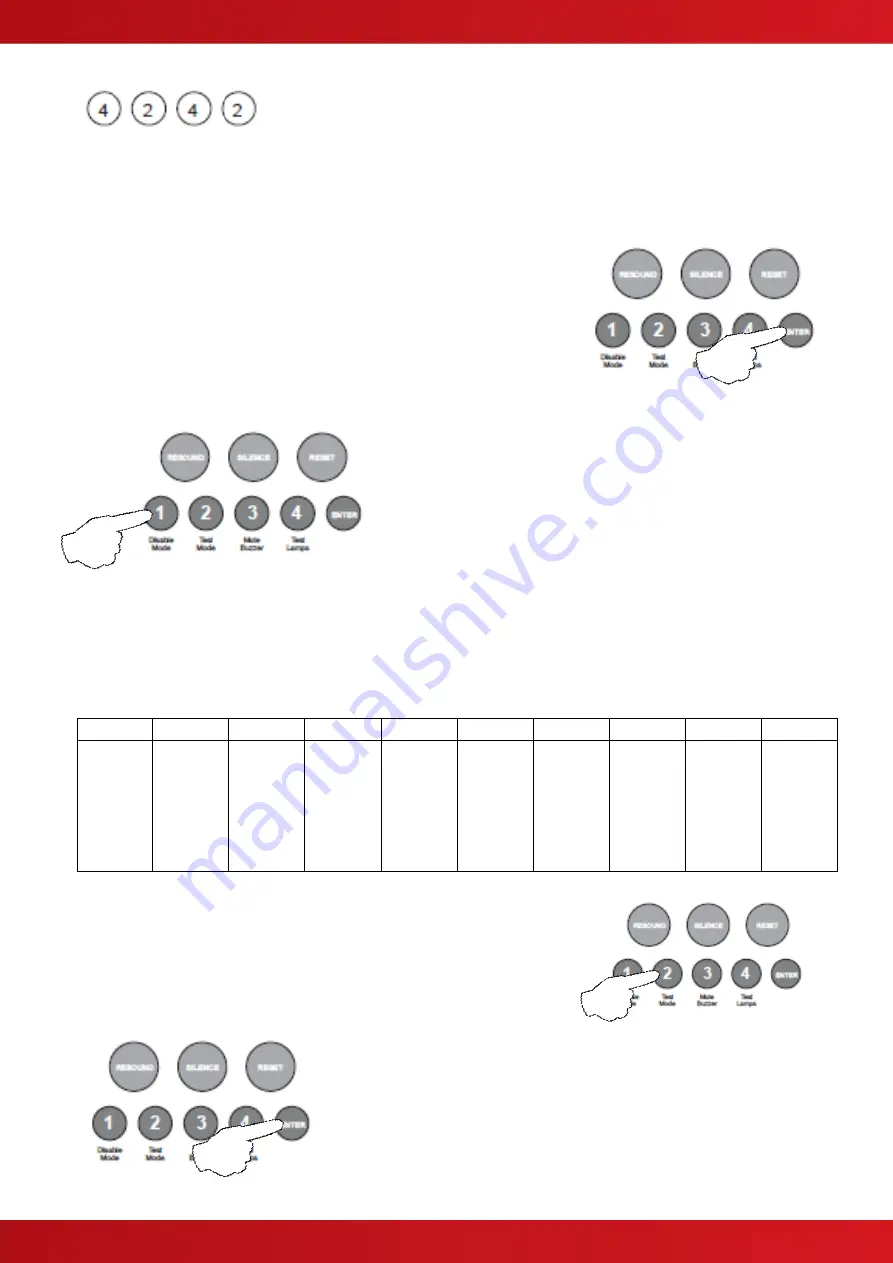
made programmable using code 4-1-4-2.
Enter the above code, 4-2-4-2 and press the ENTER button.
The zone 1 fire LED will light. This indicates setting how each of
the outputs are to respond for zone 1.
The amber, fault / disabled / test LEDs will show the current output
settings for that zone. See table below
Use button 1 to move to the zone that requires editing.
With the required zone for editing LED lit, press the ENTER
button to enter ‘editing mode’.
The fire zone 1 LED will now pulse to indicate setting the response of the first output (fire relay on main circuit
board) for the selected zone.
Use button 1 to scroll to the output that requires editing, indicated by a pulsing fire LED 1 - 10 as per table
below.
The setting of the output is indicated by the amber, fault / disabled / test LED, ON, OFF or PULSING.
LED 1
LED 2
LED 3
LED 4
LED 5
LED 6
LED 7
LED 8
LED 9
LED 10
Fire
Relay
(Main
PCB)
Fault
Relay
(Main
PCB)
Fire O/P
(Main
PCB)
Fault
O/P
(Main
PCB)
OPA
Zone ext
card 1
(Zones
5 - 8)
OPB
Zone ext
card 1
(Zones
5 - 8)
Aux
Relay
Zone ext
card 1
(Zones
5 - 8)
OPA
Zone ext
card 2
(Zones
9 - 12)
OPB
Zone ext
card 2
(Zones
9 - 12)
Aux
Relay
Zone ext
card 2
(Zones
9 - 12)
Use button 2 to change the response of the output for the selected
zone, ON, OFF or PULSING, indicated by the amber, fault / disabled /
test LED, then use button 1 to move to the next output if required.
Tip - You can use button 4 to change the response of all outputs
simultaneously to ON, OFF or PULSING (for faster programming
).
Press the ENTER button to return back to the zone selection, indicated
by a steady zone fire LED
When finished, press and hold Button 1 for 3 seconds to save setting
and exit programming mode
Enter the next programming code or disable the controls and return DIL
switch 3 to ‘OFF’.
www.acornfiresecurity.com
www.acornfiresecurity.com
Summary of Contents for Quick Zone XL
Page 5: ...5 1 2 CABINET DETAILS www acornfiresecurity com www acornfiresecurity com...
Page 8: ...8 1 4 MAIN PCB TERMINALS www acornfiresecurity com www acornfiresecurity com...
Page 15: ...15 2 3 GENERAL TWIN WIRE SYSTEM SCHEMATIC www acornfiresecurity com www acornfiresecurity com...
Page 66: ...66 This page is intentionally left blank www acornfiresecurity com www acornfiresecurity com...
Page 67: ...USER NOTES www acornfiresecurity com www acornfiresecurity com...
Page 68: ...www acornfiresecurity com www acornfiresecurity com...


