background image

2-5 

CHECK AND ADJUST 

VALVE ADJUSTING 


When you check or adjust the valve, 
do it at the low engine temperature 
(about 35

°

C) 


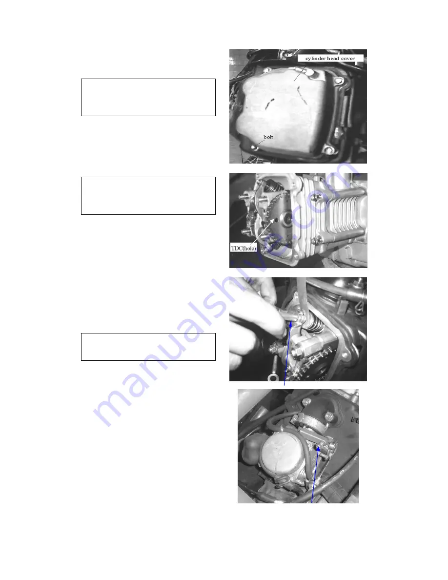
  Remove cylinder head cover. 

  Rotate the cooling fan and keep the 


gear mark of camshaft aim at the TDC 


position and the ACG flywheel “T” 


mark aim at the mark of crankcase. 


When you adjusting the valve, don’t 
invert the crankshaft, otherwise can 
not adjust the exhaust valve. 


VALVE GAP CHECK & ADJUST 
Valve gap

 IN. 

0.06 mm 


EX. 

0.10 mm 

  Loose the fixed nut and rotating the 


adjusting nut reach to the proper gap. 

  Screw the fixing nut and check the 

 gap 

again. 

  Using the valve gap adjuster to adjust 


the valve gap. 

 
ADJUSTING IDLE SPEED 


Engine idle speed adjustment have 

to do it when the engine is warm. 


  Starting the engine and connect with 


the rpm meter. 

  Adjust the idle speed adjust screw 


reach to the normal idle speed. 

 
The idle speed is 1700

±

100 rpm. 

If the idle speed is unstable or slightly 
pull the throttle the engine does not go 
smoothly then adjust the throttle valve 
stopper screw. 


valve screw adjust tool 


throttle stopper screw 


Summary of Contents for GK-125R

Page 1: ...SERVICE MANUAL GK 125R 92 61 July 04 High Power Engine HER CHEE INDUSTRIAL CO LTD...

Page 2: ...edit description is given in diagrams with Operation Sequence Highlights and Checking Arrangement for reference of the service staffs The information illustrations or contents included in this manual...

Page 3: ...m 4 Fuel system 5 Remove of engine 6 Cylinder head Valve 7 Cylinder Piston 8 Transmission Kick start 9 Final transmission 10 Crankcase Crankshaft 11 Front wheel Brake Suspension steering 12 Rear wheel...

Page 4: ...th 2 hex bolts 5 Install the fuel tank on the rear rack and fuel valve on the frame Fill up with unleaded fuel and turn the fuel valve to ON position 6 Install the seat from front Pull the lock lever...

Page 5: ...n the owner s manual 3 Engine oil 4 stroke 10W 40 is enough 4 Battery is installed properly 5 All brake cables are adjusted properly 6 Fuel tank has enough gasoline to operate 7 Check the suspension a...

Page 6: ...shall be performed in the order of first the large screws and then the small ones and from inside to outside in opposite angles by tightening the torque locks z All items must use original parts pure...

Page 7: ...rmed by over 2 people the assignment shall be conducted in coordination and safety shall be the first priority z Definition of signs The sign given in the Service Manual shall refer to the operation m...

Page 8: ...BASE 1255 mm NET WEIGHT 160 kg ENGINE TYPE 4 STROKE Single Cylinder COOLING AIR COOLED DISPLACEMENT 124 C C BORE STROKE 52 4 57 8 COMPRESSION RATIO 9 2 1 IGNITION C D I STARTER ELECTRIC KICK SUSPENSIO...

Page 9: ...flange bolt 6 8 4 0 Rear swing arm fixed nut 1 14 9 Nylon insert type Rear brake panel flange bolt 4 12 7 Front suspension fixed nut 4 10 4 0 Nylon insert type Rear suspension flange bolt 2 10 4 0 Fr...

Page 10: ...1 5 INFORMATION FOR PREPARATION The following drawing that shows the disassembling situation of the cover parts for GK 125R Go Gart...

Page 11: ...e over heat increase engine speed or continue turning at high speed Check and Adjust air cleaner blocking fuel supply isn t smooth air hole of air tank blocking exhaust pipe blocking auto plunger star...

Page 12: ...uretor sucking air loosen spark plug connecct with spark cap and contract with frame check the spark plug sparking check A C G end Reason of Trouble C D I damage pulser coil damage mixture gases too l...

Page 13: ...eing adjusting valve gap check fuel cup supply normal carburetor blocking check and adjust valve timing Reason of Trouble C D I damage ACG pulse coil damage fule filter blocking air hole of fuel tank...

Page 14: ...l for battery measure the resistance of ACG coil check the regulator check socket of regulator loosen Reason of Trouble battery damage coil damage terminal damage YL wire damage R wire damage regulato...

Page 15: ...il loosen check C D I unit socket loosen check the terminal of C D I unit unimpeded measure resistance check relate spare parts Reason of Trouble the previous spark plug damage spark plug cap loosen m...

Page 16: ...lug Gap 0 6 0 7 mm C7HSA without resistance Spark Plug Type CR7HSA with resistance 0 06mm intake valve Valve Gap 0 10mm exhaust valve Idle Speed 1700 100 rpm 0 9 L resolve the engine Engine Oil Capabi...

Page 17: ...R Gear oil R R Valve gap A A A A A A Carburetor I I C Air cleaner I R R Spark plug Clean the plug for each 3000 km replace it if necessary Brake system I I I I I I I I I I I I Belt I Suspension I I I...

Page 18: ...ether is smoothly Check the throttle lever play whether is normal The main adjusting nut for throttle play is on the side of carburetor Loose the fixed nut and adjust the play nut to proper position T...

Page 19: ...mpression air to clean the filter Check period If the vehicle often driving at the rainy or abominable surroundings please check the filter more frequently SPARK PLUG Remove the spark plug cap If the...

Page 20: ...p IN 0 06 mm EX 0 10 mm Loose the fixed nut and rotating the adjusting nut reach to the proper gap Screw the fixing nut and check the gap again Using the valve gap adjuster to adjust the valve gap ADJ...

Page 21: ...eck the ignition period Keep the engine speed about 5000rpm if the flywheel mark aim at the enter angle mark of crankcase then the ignition period is correct CYLINDER PRESSURE Remove the spark plug In...

Page 22: ...ntity check bolt Confirm the washer of the bolt whether damage Chang the gear oil Take off the quantity check bolt Remove the oil release bolt and release the oil Install the oil release bolt Confirm...

Page 23: ...and lower level Refill recommended DOT 3 brake oil when necessary Rear brake Follow the front brake procedure to check the brake pads disk and oil z Check the brake disk If the brake disk wear thickne...

Page 24: ...i Rear tire 1 68 kg cm2 24psi Checking the shaft and nut of front wheel whether loosen Checking the nut of rear wheel whether loosen STEERING Turning the steering from right side to left side check th...

Page 25: ...Check the drive chain condition z The drive chain should be check adjust and lubricate regularly z The free play of the drive chain should be between 20 30mm up and down z When install the chain clip...

Page 26: ...bling the cables and wires Remove cover parts of the GK 125 Steering Wheel z Taking off 3 hex washer face bolt z Disconnect main switch wire and neutral indicator wire Note When assembling the above p...

Page 27: ...r broken Muffler leakage Power isn t enough Muffler leakage Muffler blocking Muffler with dent Remove the muffler Taking off the nuts that connect to the cylinder Taking off the bolt that fix to the f...

Page 28: ...DIAGNOSE Oil quantity reduced Normal consumption Oil leaking Piston ring wear out or installed wrong Rubber seal of valve wear out Engine burn No oil pressure or pressure too low Oil thoroughfare blo...

Page 29: ...otor oil will flow more easily if the engine is warm The oil release nut is under R crank case cover Take off the oil filter cover can have better release of the oil Check the O ring of oil filter cov...

Page 30: ...d starter clutch TLCT125 04 Use special tool to loose the starter clutch lock nut Attention the lock nut is the thread The lock nut is the left thread type Take off 2 bolts of the oil separator and re...

Page 31: ...d remove the oil pump ass y Disassembling Take off the screw on oil pump and disassembling the oil pump Check Check the gap between the pump body and outer rotor The gap limit is 0 10 mm Check the gap...

Page 32: ...angle position match with the inner rotor Install the dowel pin Siting the dowel pin and the pump cover Locking the screw After installed turning the pump slightly and confirm the function is normal I...

Page 33: ...lts Mounting the starting clutch gear and starter clutch Mounting the gasket and dowel pins z Use special tool to fix the starter clutch lock nut TLCT125 04 Mounting the R crankcase cover with 5 fixed...

Page 34: ...uel level too high Muffler make explore noise when deceleration Too much air Air stop valve abnormal Too thin of F A mixture at idle speed Ignition not continuously when accelerate Ignition system abn...

Page 35: ...t chamber Remove the fuel tube and vacuum pressure tube Loose the adjusting and fixed nut of throttle cable Removing the throttle cable Loose the clamp on intake manifold and remove the carburetor AUT...

Page 36: ...auto plunger starter connect with terminal and the GR wire connect with the terminal of battery After about 5 min the auto plunger starter warm up then the needle will go up Otherwise the auto plunger...

Page 37: ...g the film into carburetor Put the spring cover back then locking 2 screws Attention When mounting the film the dint of the film have to aim at correct position of carburetor VACUUM PRESURE CHAMBER Re...

Page 38: ...m film and piston into the carburetor body Keep the piston of film at top Position throttle full open position The upheaval of film aim at the dint of carburetor body Mounting the cover and locking th...

Page 39: ...jet seat nozzle pilot jet and the fuel adjusting screw Beware not to damage the jet and adjusting screw Before remove the fuel adjusting screw remember mow many turns into the end To avoid the damage...

Page 40: ...e pilot jet main jet seat main jet and fuel adjusting screw Before remove the fuel adjusting screw remember turns of setup into the end position The normal setup is 3 1 8 3 4 turns out Install the flo...

Page 41: ...djust the fuel screw again Remember the setup before disassembly Use neutral gear to adjust the carburetor Smoothly turn the fuel adjusting screw into the end then return back to the standard setup Th...

Page 42: ...d the fuel come out then the valve film inside the fuel cup is damaged AIR CLEANER ASSEMBLY Release the clamp screw which connect to the carburetor Take off the air hose connect to the final transmiss...

Page 43: ...en fuel overflowed Operation Parts Name Q ty Remarks 1 2 3 4 5 6 7 8 Disassembly Pan phillips bolt 6 15 Fuel tank net Hex bolt 6 16 Clip Fuel tube Hex washer face bolt 6 16 Fuel cap Fuel tank comp 4 1...

Page 44: ...e engine Crank shaft case Crank shaft Exchange bearing of final transmission mechanisms Disassembly of Engine Disassembly of external cover of body Disassembly of throttle valve and cable Operation Pa...

Page 45: ...f engine plain washer of engine Hex washer face bolt of engine Hex washer face bolt of engine Engine 1 1 1 1 1 1 WARNING z Actually for brace the frame avoid body turn inside out Assembly 8 1 WARNING...

Page 46: ...y of Muffler Operation Parts name Q ty Remarks 1 2 3 4 5 Disassembly Take off the engine Ass y Nut cap 6mm Hex washer face bolt 8 32 Exhaust bracket Muffler 1 1 2 1 1 Assembly 5 1 Assembling with sequ...

Page 47: ...abnormal Leaking of cylinder head gasket Bottom of cylinder head damaged Wrong installation of spark plug Valve gap adjustment 0 12 mm Compression Pressure too high Too much carbon residue inside comb...

Page 48: ...juster cover screw Locking the inside small screw of the cam chain adjuster that the locking direction is clock wise Let the T mark on ACG fly wheel aim at the crankcase sign The big hole on camshaft...

Page 49: ...haft holder Unscrew the bolts cross wise for 2 3 times Remove the camshaft holder and dowel pins Remove the cam chain gear from cam chain then take out camshaft Check the cam surface to see if it s we...

Page 50: ...ck arms and rock arm shafts If the sliding face of rock arm wear out then check the cam surface of the cam shaft Check the inside diameter of camshaft holder on rock arm activity part Replace above 10...

Page 51: ...ck the movement of the one way plate Disassembly the cylinder head Remove camshaft Remove carburetor Remove exhaust muffler Remove carburetor intake manifold Remove cooling fan cover Remove bolts scre...

Page 52: ...ful do not drop anything into engine Valve spring holder tool TLCT125 02 Disassembly cylinder head Use valve spring holder tool to remove the spring holder cotter spring valve and seal Valve spring mu...

Page 53: ...t s burned or banded Check the movement between valve and guide is smooth or not Valve outside diameter working limit Replace under 4 9 mm Cylinder head assembly Install valve seal spring seat Install...

Page 54: ...r head Install camshaft Assembly of camshaft holder On top of camshaft holder EX mark is for exhaust side Assembly rock arm stopper plate rock arm shaft Beware not to damage the valve Cutting edge of...

Page 55: ...nstall dowel pins Put the camshaft holder washers and bolts then tie up the bolts on cylinder head Locking torque for cylinder head nuts 2 0 kg m Adjust gap between valve and valve screw Counter Clock...

Page 56: ...tie up the cover screw Replace new O ring on cylinder head cover before assembly the cover Tie up cylinder head cover fixed bolts cylinder head cover ring must put into the correct position The O ring...

Page 57: ...linder piston wear out or damaged Compression pressure too high Piston or combustion chamber stocks with carbon material Exhaust with white smoke Piston ring wear out burn or broken Cylinder piston we...

Page 58: ...Clean the gasket stick on cylinder REMOVE THE PISTON Take off piston pin clip Beware not to drop off the clip into crankcase Take out piston pin and remove the piston Check the piston piston pin and p...

Page 59: ...ing into cylinder Measure the opening gap of the piston ring Working limit Replace if over 0 5mm Measure the hole of the piston pin Working limit Replace if inside diameter is over 15 04mm Measure out...

Page 60: ...e sure the rings rotate freely after install into piston Piston installation Clean the gasket stick on top of crankcase Do not drop off any material into crankcase Install piston piston pin and rings...

Page 61: ...e careful not to damage or band the piston ring The opening section of piston rings should not be the same with piston pin and set into 1200 to each other Install 2 bolts of the cylinder Install cam c...

Page 62: ...icle does not move after engine start up Drive belt wear out Drive face comp damage Clutch lining wear out Driven ass y spring defect Power insufficient Drive belt wear out Driven ass y spring defect...

Page 63: ...cover Remove the gasket and dowel pins Assembly Install the gasket and dowel pins Install the L crankcase cover Do not pull out kick starter spindle and press the spindle firmly when All brackets for...

Page 64: ...able drive face assembly Check Check the drive belt to see if it s damaged rubber fiber came off or any other abnormal wear out Check the width of drive belt Working limit Replace if under 19 0mm Use...

Page 65: ...side diameter of weight rollers Working limit Replace if outside diameter is under 17 3 mm Check Check inside diameter of the movable drive face Working limit Replace if over 24 10mm Check the damage...

Page 66: ...9 4 TRANMISSION KICK START Assembly diagram Put the weight rollers into movable drive face Install the cam plate Put the boss into drive face assembly boss movable drive face cam plate...

Page 67: ...e belt on the boss of movable drive face assembly Install the fixed drive face washer and nut Use fixture to hold the drive face and tie up the nut Locking torque 5 5 kg m Drive belt and drive face ca...

Page 68: ...ck Check the cover if wear out or damaged Check the inside diameter of cover Working limit Replace if over 125 5 mm Check the clutch lining if wear out or damaged Measure the thickness of the clutch l...

Page 69: ...the kick starter stop plate and the starter spring Pull out the starter spindle assembly Remove the starter idle gear assembly Disassembly Disassembly starter spindle assembly Check if the spindle wea...

Page 70: ...re is any damage or wear out Installation The pin on starter idle gear shaft should aim at the correct position of L crankcase The pressed line on starter gear should aim at the pressed mark of idle g...

Page 71: ...NAL TRANSMISSION GK 125R TROUBLE DIAGNOSE Engine starts but vehicle does not move Transmission gears broken Transmission gears burns out Gear oil leaking Too much gear oil filled Oil seal wear out or...

Page 72: ...the bolts and pull out mission cover Remove the mission cover together with the gear set Remove the gasket and dowel pins Remove the hex flange bolt shift lever and contact plate CHECK Check if the s...

Page 73: ...ake out the final gear and gear shaft Take out the main gear shaft and main gear Check final transmission gearbox Check the wear out or damage of gears shafts and bearings When bearings has been damag...

Page 74: ...bearings Final transmission installation Install the main gear assembly and final gear shaft into crankcase Install the final gear onto shaft Install new gasket and dowel pins Install the mission cov...

Page 75: ...11 0 CRANKCASE CRANKSHAFT TROUBLE DIAGNOSE Engine noise Loose of crankshaft bearings Loose of bearings inside crankshaft connecting rod...

Page 76: ...ick start driven gear special TLCT125 05 Kick start driven gear puller Take off 2 bolts on R crankcase Disassembly L R crankcase Do not damage the gasket area of the crankcases This will avoid the oil...

Page 77: ...et which between crankcases Do not damage the gasket area of the crankcases Remove both oil seals from L R crankcases CRANKSHAFT Check the tolerance between connecting rod and crankshaft Working limit...

Page 78: ...assembly if necessary Crankcase assembly Press in the oil seal for L R crankcases and do not damage the inner part of the seals Install the cam chain into L crankcase Install the crankshaft into L cr...

Page 79: ...kick start driven gear Install the cam chain adjuster guide Install the new O ring on the fixed bolt for cam chain adjuster O ring must be greased and tie up Locking torque 1 0 kg m The O ring must fi...

Page 80: ...ball bearing broken Brake efficiency abnormal Brake lining wear out Brake pads adjust not correct or wear out Brake drum wear out Tire wear out Steering handle not straight Loose not correct adjustmen...

Page 81: ...bly front wheels L R Rubber cover Cotter pin Slotted nut Plain washer 12 40 4 5 Disassembly front brake drum Spacer tube Hex washer face bolt 10 20 Front brake drum Rim 7 5 2 Tire 18 7 7 2 2 2 2 2 8 2...

Page 82: ...sher 10 20 2 Upper a arm ass y Hex slotted nut 12mm Plain washer 12 22 2 Nylon nut 10mm Hex washer face bolt 10 175 Lower oscillation arm Strain spring Front brake shoe comp Right knuckle ass y left k...

Page 83: ...G Disassembly of Suspension Arm seq Operation Parts name Q ty Remarks 1 2 3 4 Disassembly L R Hex washer face bolt 10 40 Nylon nut 10mm Front cushion Hex washer face bolt 10 179 4 8 2 4 Assembly 12 1...

Page 84: ...eering shaft ass y Hex bolt 5 12 Split spring pin 6 24 Internal cir clip Washer 26 39 1 5 Steering drive gear Bush Hex flange nut with serration 8mm Hex washer face bolt 8 48 Bush Spacer Rack cover Ra...

Page 85: ...n 2 15 Brake pedal comp Hex washer face bolt 6 16 Cable bracket Hex nut 6mm Pedal fix bracket Brake arm pin Drive nut Rear brake fixture Brake elbow Stop switch spring Stop switch ass y Brake rod Acce...

Page 86: ...arks 1 2 3 4 5 6 7 8 9 10 11 12 Disassembly reverse Pan Phillips bolt 5 10 Outer cover Fix shift Reset spring Collar Hex flange nut with serration 8mm Shift lever Shift plate Seat lock ass y Reverse c...

Page 87: ...f rear rim damaged z Rear wheel axle damaged z Swing arm sub Ass y damaged z Rear rim bearing defected Rear suspension too soft z Spring too soft or adjust not correct Brake efficiency abnormal z Brak...

Page 88: ...sassembly L R Rubber cover Cotter pin 3 32 Scotch nut12mm Plain washer 12 40 4 5 Front brake drum Hex washer face bolt Nylon nut 8mm Spring washer 8 5 13 2 Hex washer face bolt 8 20 Bearing holder Rad...

Page 89: ...embly Rear Brake Hex washer face bolt 8 12 Rear brake cylinder sub ass y Ladder bolt 6 14 2 5 Front brake disc cover Brake hose hex nut 10 22 Plain washer 10 14 5 5 Rear brake hose Hex washer face bol...

Page 90: ...12 13 Disassembly rear axle Plastic spacer Hex washer face bolt 8 20 Brake disc Retainer Rear sprocket hub Hex nut M33 14 Hex washer face bolt 8 20 Rear sprocket Rear sprocket hub Plastic spacer Plas...

Page 91: ...et spring Nylon nut 10mm Hex washer face bolt 10 32 Spacer tube Idle sprocket Radial ball bearing Plain washer 10 17 2 5 Nylon nut 8mm spring washer 8 2 18 0 8 idle sprocket shift idle sprocket nylon...

Page 92: ...chain cover External cir clip Plain washer 12 18 1 2 Chain roller Nylon nut 8mm Plain washer 8 14 2 Plain washer 8 2 18 0 8 idle sprocket shift idle sprocket spring idle sprocket bracket nylon nut 10m...

Page 93: ...mounting bracket Nylon nut 10mm Plain washer 10 22 2 Hex washer face bolt 10 55 Hex washer face bolt 8 40 Hex washer face bolt 8 20 R cross bar Disassembly Rear cushion Nylon nut 10mm Plain washer 10...

Page 94: ...ks 1 2 3 4 5 6 7 Disassembly engine rack Nylon nut 10mm Plain washer 10 22 1 5 Hex washer face bolt 10 48 Rubber bush Hex flange nut with serration 12mm Hex washer face bolt 12 65 Engine bracket ass y...

Page 95: ...y if recharged before installed Do not unplug the electrical components from wire hardness when the current is working This will cause too high of voltage and damage other compounds such as rectifier...

Page 96: ...Connect the wire RD than the wire GR to avoid short circuit Installation based on reversed procedure CHARGE Connection Charger to battery Charger to battery Avoid any flaming material around the batt...

Page 97: ...Use RPM meter to measure the engine revolution Slightly increase the engine revolution to measure the voltage and current Charge voltage and current 13 5 15 5V 1 0 A under 5000rpm If the value does no...

Page 98: ...e lighting for charge coil of ACG can be done on engine assembly Measure the resistance between ACG yellow wire and ground green wire Resistance 0 1 1 0 20 C Check resister Measure the resistance betw...

Page 99: ...Use flywheel puller to remove the generator flywheel special TLPT 01 Remove the semi cycle key Unplug the AC generator connecting wires Remove the wire fix bracket Take off the pulsar coil fixed bolt...

Page 100: ...any nuts or screws which will damage the generator coil Install the flywheel with spanner tool and tie up the fixed nut Locking torque 5 5 kg m semi Cycle key IGNITION SYSTEM HIGH TENSION COIL Remove...

Page 101: ...Standard 0 1 1 0 20 C If the resistance reads then replace new coil Measure the resistance between the spark plug cap and one terminal Standard 7 12 K 20 C with cap Remove the spark plug cap and measu...

Page 102: ...ctivity between each terminal Color R BR BK W GR GR W GR OFF ON START Remove main switch Disconnect main switch wire Pull the main switch Bracket inside front cover Push the stopper on main switch und...

Page 103: ...14 8 ELECTRICAL DEVICE z Check Left Switch HORN Color GR PI FREE PUSH WARNING LIGHT Color DBR BR W DGR x Engine start Color GR BK W Restore Pull...

Page 104: ...9 ELECTRICAL DEVICE Head Light Witch Color BL W YL BL Exchange of Bulbs Head light bulb z Press down the bulb base and turn left to change head light bulb head light bulb head light wire head light co...

Page 105: ...t bulb Brake light bulb Rear direction light bulb Remove 2 screws pull out the light cover then change bulb Remove R L screw on direction light cover pull out the cover then replace the bulb SIGNAL Li...

Page 106: ...14 11 ELECTRICAL DEVICE pilot lamp z Press down the bulb base and turn left to change bulb SPEEDOMETER z Remove speedometer bracket NUT BOLT speedometer...

Page 107: ...ect the wire Check the movement of starting motor shaft Check the motor rotation by connecting full charged battery direct to the starting motor When using the battery test motor be sure to hold the m...

Page 108: ...ng full charged battery connect with the yellow red and green yellow wires of the relay When the battery connect to starter relay the current should pass between 2 terminals STARTER CLUTCH Disassembly...

Page 109: ...f starter drive gear Working limit Replace if over 32 1mm Check the needle bearing and replace if damaged Disassemble the starter clutch body Check 3 springs and working surface of the clutch body wit...

Page 110: ...ody and cover The clutch cover or 3 bolts should use lock tie glue to ensure the tightness Grease the needle bearing and install into the clutch body with starter drive gear Install the starter clutch...

Page 111: ......

Reviews: